Summary of Arduino Laser Tag – Duino Tag
Duino Tag is a customizable, Arduino-based laser tag system using infrared light for safe combat simulation. The project involves modifying second-hand light guns or building from scratch to create a modifiable platform for office, woodland, or suburban skirmishes. It emphasizes community contribution and future upgrades, offering a low-cost alternative to commercial systems while providing audio, visual, and sensor feedback for an immersive gaming experience.
Parts used in the Duino Tagger:
- Arduino
- Light Gun
- Coloured LED's (preferably 30mA+)
- IR sensors
- At least 2x IR LED's matched to the IR receiver (preferably 100mA+)
- Peizo sounder
- Power transistor /MOSFET
- Solder, resistors, capacitors
- Scrap plastic
- LED bar graph driver chips
- Hats / helmets / headbands to mount sensors on
Duino tagger– General introduction
Duino tag is a laser tag system based around the arduino.
Finally a laser tag system that can be tweaked modded and hacked until you have the perfect laser tag system for office ordnance, woodland wars and suburban skirmishes.
Laser tag is combat game like paintball or airsoft without the pain, it uses infrared light (IR) to simulate the tagging / shooting of other players or targets.
I have been working on this project for a while, but don’t see it as over, I just though it was time to get more people involved. Hopefully this instructable will be near enough finished in time for me to enter it in the arduino competition, although I expect the instructable will need editing and tweaking for some time to come.
This instructable aims to provide you with the information you will need to go out and build your own duino tagger.
This instructable focuses on how to build a duino tagger by modifying a light gun but with a bit of extra work you could build you own gun from scratch.
This instructable does not look in too much detail at the software / code side of the project, although a working code based on the miles tag protocol is provided.
For those wishing to learn about duino tagger programming I suggest you start at the excellent tutorials found at A Terrible Idea.
Thoes experience arduino users will probably find the overview page (Step 1) and code pages (Step 8) the most useful, newer arduino users may need to take a closer look at the instructable and the links provided.
I hope many of you will find this instructable useful and will go on to build your own duino taggers. There is much scope for improving and upgrading this system outlined here. If you do go on to improve on this duinotagger please share your work and hopefully in time the system will evolve into a much richer gaming experience.
Youtube videos of my duino taggers:
This video shows me using the second duino tagger I made to shoot at a talcapult target I have been working on. I hope to make an instructable about the talcapult soon.
Step 1: Overview
Key parts of a duino tagger:
IR Transmitter system
What – Transistor amplifier, high power IR LED and a lens to give a well focused IR beam.
Why – To give the tagger means of tagging / shooting other players as well as communicating game information. The transmitter amplifies the transmission signal from the arduino and transmits it using an IR LED, lenses are used to make the signal very directional in order to make the guns behave like guns and make long range transmissions possible.
Sound
What – Peizo Sounder (& mini sound recorder / playback electronics from greetings card)
Why – It’s nice to have some audio feedback from the system. Sound effects to let you know when the tagger has been shot or run out of ammunition or lives.
Receivers
What – Standard IR receiver module and power regulation capacitor
Why – So the gun knows when it has been shot. This design in this instructable looks at using 3 sensors 1 on the gun as well as front and rear head sensors.
Visual Effects and lights
What – LED’s and bar graph driver circuits
Why – It is nice to get visual feedback on game information, eg lights to let you know when you have been shot.
Cost
To make this section internationally friendly; at the time of writing: £1 GBP = $ 1.6 USD = 1.1 EUR
Assuming you already own an arduino the basic extra components for this project can be bought for around £10.
Now is a great time to try to build a duino tagger as it is easy to get hold of cheap second hand light guns. Light guns are the guns that you can use with computer games, many of them don’t work with modern LCD screens and so there are a lot of them going cheap on ebay and else where. I bought two light guns each cost about £4 one off ebay one from a charity shop. Light guns are a great starting point for this project as they provide the optics, switches and case required for the build.
You will need:
Arduino
Light Gun
Coloured LED’s (preferably 30mA+)
IR sensors
At least 2x IR LED’s matched to the IR receiver (preferably 100mA+)
Peizo sounder
Power transistor /MOSFET
A few electronics basics: solder, resistors , capacitors.
You may also want
Scrap plastic
LED bar graph driver chips
More LED’s
Record your own message greetings card
Hats / helmets / headbands to mount sensors on
Step 2: Basics
Key parts of a duino tagger:
IR Transmitter system
What – Transistor amplifier, high power IR LED and a lens to give a well focused IR beam.
Why – To give the tagger means of tagging / shooting other players as well as communicating game information. The transmitter amplifies the transmission signal from the arduino and transmits it using an IR LED, lenses are used to make the signal very directional in order to make the guns behave like guns and make long range transmissions possible.
Sound
What – Peizo Sounder (& mini sound recorder / playback electronics from greetings card)
Why – It’s nice to have some audio feedback from the system. Sound effects to let you know when the tagger has been shot or run out of ammunition or lives.
Receivers
What – Standard IR receiver module and power regulation capacitor
Why – So the gun knows when it has been shot. This design in this instructable looks at using 3 sensors 1 on the gun as well as front and rear head sensors.
Visual Effects and lights
What – LED’s and bar graph driver circuits
Why – It is nice to get visual feedback on game information, eg lights to let you know when you have been shot.
Cost
To make this section internationally friendly; at the time of writing: £1 GBP = $ 1.6 USD = 1.1 EUR
Assuming you already own an arduino the basic extra components for this project can be bought for around £10.
Now is a great time to try to build a duino tagger as it is easy to get hold of cheap second hand light guns. Light guns are the guns that you can use with computer games, many of them don’t work with modern LCD screens and so there are a lot of them going cheap on ebay and else where. I bought two light guns each cost about £4 one off ebay one from a charity shop. Light guns are a great starting point for this project as they provide the optics, switches and case required for the build.
You will need:
Arduino
Light Gun
Coloured LED’s (preferably 30mA+)
IR sensors
At least 2x IR LED’s matched to the IR receiver (preferably 100mA+)
Peizo sounder
Power transistor /MOSFET
A few electronics basics: solder, resistors , capacitors.
You may also want
Scrap plastic
LED bar graph driver chips
More LED’s
Record your own message greetings card
Hats / helmets / headbands to mount sensors on
Step 3: Modding the light gun
Modding the light gun
The details of the light gun modifications will depend on the light gun.
Here are some general guidelines and ideas:
Useful parts to leave in the:
Switches
Trigger
LED’s
Lense
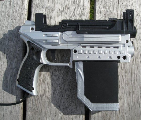
Adding storage space to your light gun: Fitting things in can be difficult, you might also not wish to put your arduino inside the gun. I wanted to be able to easily remove my arduinos from my duino taggers so I could use them in other projects.
On one of my duino taggers (MK1 gun) I cut holes in the case for the arduino nano pins to go through and mounted a socket on the inside of the gun so the arduino plugged on the outside of the gun. On my Mk2 gun I added an external case for the arduino and tried to make it look like an ammunition clip. The case / ammo clip was made from plastic I got from a cheap ring binder folder and its cover is held in place by a strong magnet.
Step 4: Transmitter
You will need:
IR LED: Look for an LED with a narrow viewing angle (to ensure as much of the IR light makes it through the optics).
Higher power the better.
Pick LED’s with a wavelength that matches your IR receivers.
Get some spare LED’s as they are operated above their rated current so may burn out.
You can just attach an IR LED (with a current limiting resistor) to an output pin on the arduino and it will be able transmit, but the range of the duino tagger won’t be very impressive. In order to improve the range of the duino tagger amplification is needed.
The basic amplifier I made was a simple transistor circuit (circuit diagram provided), you may wish to consider a mosfet instead of the transistor.
Current through the LED: I aimed for about 300mA current through the IR LED. This is more than the rated current for the LED, but the LED seems to be able to cope because you are only pulsing the high current for a short time. If you are using the 5V supply from the arduino to power the LED it can only provide about 400/500mA so using 300mA for the IR transmitter Led does not leave too much for the other LED’s and speakers etc, so bare this in mind when designing building your duino tagger, it might be a good idea to add a voltage regulator capable of supplying higher currents.
Optics
You will need to use a lense to focus the IR beam, you can use the lense that came with the light gun. You can use a red LED to work out where to put the IR led to get a good focused beam.
For more details see the miles tag site.
Step 5: Receiver
The receivers are for detecting when the tagger has been shot and receiving game data.
The receivers are standard IR remote control receivers like you would find in a TV remote.
There are quite a few different receivers you can choose from I went for the cheapest I could find the main things to consider are:
Will you be able to find a matching LED, one that works at the same light wavelength that the sensor is optimised for, If you don’t match the LED and receiver the tagger range will be reduced.
If you want to be able to use your duino tagger to be compatible with any other duino tag, laser tag or miles tag systems you will need be working at the same modulation frequency and light wavelength.
Most of the IR receivers work in a very similar way and you will be able to wire then up the same as the circuit diagrams in the pictures.
The output pin of the receiver drops to a low voltage when a signal is being received. The outputs from multiple sensor can be connected and one sensor receiving will still cause the combined output signal voltage to drop.
The receivers work on there own and can be connected directly to the arduino, but they are much more reliable when used with capacitors to regulate the power supply and pull up resistors.
Step 6: Sound Effects
Audio / Sound Effects
Adding sounds to the system makes for a better game experience. It is nice to have sounds for the:
Fire, been shot, start, dead / out of lives sound, out of ammo……….
Ideally to add sounds you would use a fully featured audio shield like the wave shield.
keep me updated if you try this.
For simplicity and to save on build cost I chose just to use a piezo buzzer, this works well for most of the system tones, but it is tricky to use the piezo to make a good gun shot noise.
If you are interested in the details of making sounds on an arduino usining a piezo buzzer have a look at the melody example.
One simple and cheap way of adding better sound effects to your duinotagger is to use the electronics form a “record your own message” card. You can get the cards for £2/3 off ebay.
Mini instructable.
1. Remove the electronics from the greetings card.
2. Play around with the electronics for a while to get an idea for what it all does.
3. The card circuit will play the recorded sound as soon as it is powered. The card circuit draws about 50mA so can be powered direct from an arduino output, ideally you would power it at 3V to the card circuit (the same as the button cells that powered it previously), but I did not encounter any problems powering it with the 5v direct form the arduino. If you found that 5v was damaging the circuit you could diodes to reduce the voltage (just make sure you pick ones able to cope with 50mA).
4. Connect the arduino output to where the positive on the batteries originally powering the circuit would have been and connect the arduino ground to where the battery negative was. You should now find when the arduino output goes high the sound recorded on the card circuit is played.
 Methods of recording the sound to the card circuit, you could just use the microphone (peizo transducer) that came with it or for slightly better sound quality you could use a potential divider (eg 10k pot) to connect it up to a computer and record directly to the circuit.
You may wish to consider adding an audio amplifier to make the sound effects a bit more impressive.
Step 7: Visual effects / Lighting
Display / Visual Feedback
It is nice to have visual feedback for things like ammunition and lives there are a few ways you could do this: the main being using LED’s or an LCD to display the information.
I chose to uses LED’s, and there is provision for using LED’s in the code provided.
The code varies two of the arduino’s PWM pins( ammoPin and lifePin) dependant on the ammunition and life.
The PWM pins can be used to power LEDs and the more life or ammo the player has the brighter the LEDs will be alternatively the PWM output can be used to drive an bar graph driver chip like the LM3914N
The PWM output can not be used to directly drive a bar graph driver chip, the PWM signal needs to be smoothed to give an analogue output, this can easily be done using an RC low pass filter.
For more detail: Arduino Laser Tag – Duino Tag
- What is the Duino Tagger?
A laser tag system based around the Arduino that uses infrared light to simulate tagging without pain. - Can I build this system without buying new parts?
Yes, you can buy cheap second hand light guns on eBay or from charity shops to use as the starting point. - How do I improve the range of the transmitter?
You need to use a transistor amplifier or MOSFET to boost the signal from the Arduino before it reaches the IR LED. - What is the best way to get audio feedback?
You can use a piezo buzzer for simple tones or extract electronics from a record your own message greetings card for custom sounds. - Does the receiver work directly with the Arduino?
The receivers can connect directly but are much more reliable when used with capacitors to regulate power and pull up resistors. - How can I display ammunition and life levels visually?
You can use LEDs powered by PWM pins where brightness indicates status or drive a bar graph driver chip like the LM3914N. - Why should I match the IR LED wavelength to the receiver?
Mismatching the LED and receiver will reduce the effective range of the duino tagger system. - Is the code provided in detail?
No, the article provides working code based on the miles tag protocol but suggests external tutorials for detailed programming learning.