Summary of Arduino Laser Harp
A framed laser harp project uses nine laser beams (7 notes plus octave up/down) and photoresistors to trigger an Arduino sending MIDI Note On messages to music software. Lasers strike photocells; interrupting a beam makes the Arduino send MIDI over a DIN cable through a MIDI interface to a laptop. The build involves laser and Arduino circuits, enclosure woodworking, wiring, soldering, and safety precautions (do not look into lasers; use ≤5mW). Project resources include mnsman’s template and Chris Ball’s instructable; code was borrowed from mnsman.
Parts used in the framed laser harp:
- Laptop (running MIDI software)
- Arduino Uno
- MIDI interface (MIDIsport 4x4 used)
- USB A to B cables (2)
- 5 pin DIN MIDI cable
- Nine 5mW red laser diodes
- Nine 50Ω photo-resistors (LDRs)
- Nine 4.7K Ω resistors
- 220Ω resistor (for MIDI plug)
- Arduino Proto Shield (bare PCB)
- Pin headers (~15)
- 22 gauge electrical wire spool
- ON/OFF switch (optional)
- 5 pin DIN female connector
- 5V power supply (for laser modules)
- Soldering iron and solder
- Wire cutters
- Wire strippers
- Glue gun with hot glue sticks
- Electrical tape
- Tape measure
- Marker
- Breadboard
- Jumper wires
- Tac putty tabs
- Scissors
- Wood for enclosure: 1x pine, 1/4" MDF, 1/2" plywood
- Table saw
- Band saw or jig saw
- Screw gun or pneumatic stapler
- Drill with bits
- Wood glue
- Spatel
- Joint compound
- Paint
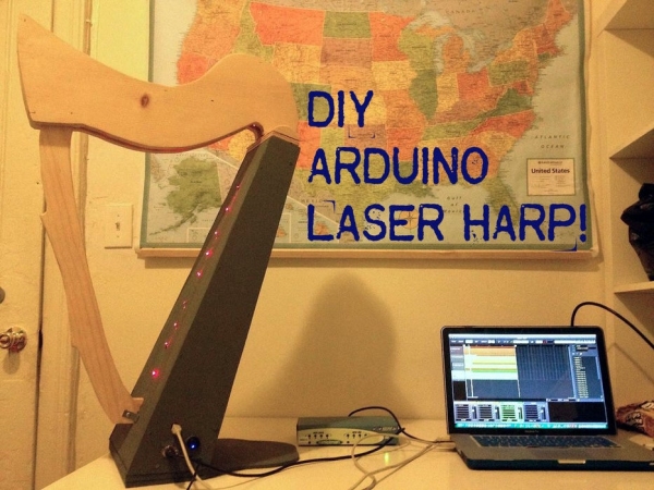
A couple of weeks ago I presented my culmination project, framed laser harp, at New York City College of Technology. Work on it was so interesting for me, that I decided to share it here. I am an Arduino amateur and don’t have any professional experience in electrical engineering or programming. Neither am I a musician. Probably that’s why I had so much fun: when you are moving blindly, you can’t see the ground anyway:)
So, why laser harp? First of all, lasers are always cool. But laser beams making sounds were some kind of sorcery for me ever since I encountered a huge Arc Harp at Burning Man 2012. I was obsessed with the idea of making my own laser instrument, and finally got a chance to do it.
After quite a bit of a research, I finally found a wonderful starting point – very well documented project template made by mnsman. Although I modified many things, my project heavily relies on mnsman’s work. For example, the code I’m using is entirely taken from his project.
Another extremely helpful resource was Chris Ball’s instructable. It has very comprehensive wiring diagrams and is great in explaining the working principle.
Laser Harp project is pretty ‘multidimensional’, because it involves different types of skills, such as wiring and soldering, drafting, woodworking, familiarity with Arduino and MIDI, and more. At the same time, everything is very flexible: you could design and build your own enclosure, change the number and function of laser modules, modify the code, etc.
A note on safety: NEVER LOOK DIRECTLY INTO THE LASERS. Also, avoid using high power laser modules (more than 5mW) for this project.
Good luck, and please let me know of any inaccuracies (either descriptive or grammatical) in this instructable.
Step 1: Working Principle
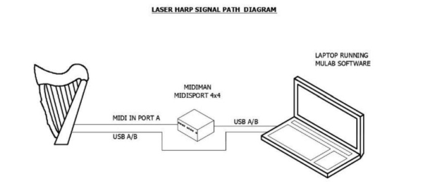
A laser harp is an electronic musical instrument, consisting of several laser beams (9 in this case: 7 notes, Octave Up, Octave Down) to be blocked in order to produce sound. In a framed version of the harp, each beam strikes a photocell, and when the player’s hand interrupts it, the sensor prompts an Arduino microcontroller to send a MIDI “Note On” (logic HIGH) message.
In this particular laser harp MIDI signal is sent from the Arduino through MIDI interface to the laptop running MIDI software (I used MuLab, because it’s free and simple). The second USB A/B cable just powers up the Arduino (it is possible to use a 5V power supply or couple of batteries instead).
Step 2: Parts and Tools
Electronic Components
- 1 x Laptop (running MIDI software);
- 1 x Arduino Uno;
- 1 x MIDI interface (I used MIDIsport 4×4, because I had this at home);
- 2 x USB A to B cables (Arduino to laptop; MIDI interface to laptop);
- 1 x 5 pin DIN MIDI cable (harp to MIDI interface);
- 9 x 5mW red laser diodes;
- 9 x 50Ω photo-resistors (LDRs);
- 9 x 4.7K Ω resistor (in series voltage dividers with photo-resistors);
- 1 x 220Ω resistor (for MIDI plug);
- 1 x Arduino Proto Shield (bare PCB; to solder all wires into the board, instead of just inserting them into the Arduino itself);
- ~ 15 pin headers (to attach a bare PCB shield to the Arduino)
- 1 spool x 22 gauge electrical wire;
- 1 x ON/OFF switch (optional, for harp);
- 1 x 5 pin DIN female connector (harp to MIDI interface);
- 1 x 5V power supply (for laser modules);
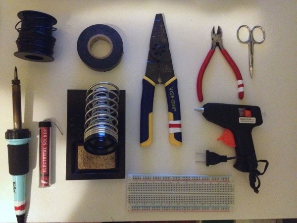
Tools and Supplies
- Soldering iron and solder;
- Wire cutters;
- Wire strippers;
- Glue gun with hot glue sticks;
- Electrical tape;
- Tape measure;
- Marker;
- Breadboard (for circuit prototyping);
- Jumper wires (for circuit prototyping);
- Tac putty tabs (to hold laser modules in place when aligned);
- Scissors;
Enclosure
The enclosure design is entirely up to you. I had access to a professional shop, and decided to give my harp a ‘real’ look. I will not describe the process of building the enclosure in this instructable, however, the drawings I used will be provided (as is). I used 1x pine for the neck and the column, 1/4″ MDF for the sides of the ‘box’ and the stand, and 1/2″ plywood for the top and bottom of the ‘box’. I found this shape to be inefficient, because of the difficulties in laser modules/photodiodes alignment. I highly recommend to come up with another shape, something where the lasers and photodiodes form strait vertical lines when aligned. It was for me a real nightmare to align lasers and diodes at an angle.
If you decide to replicate this shape, you will need the following tools and supplies:
- Table saw;
- Band saw (jig saw may be used);
- Screw gun or pneumatic stapler;
- Drill with different drill bits (for the photo-resistors, power button and harp outputs placement);
- Wood glue;
- Spatel;
- Joint compound;
- Paint;
Step 3: Schematics
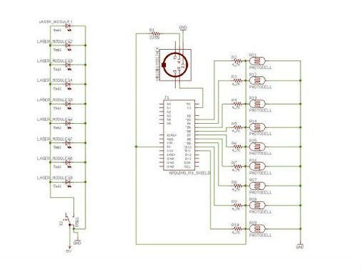
There are two independent circuits: one for the laser modules (with power button and a 3-5V power supply), and another one for the Arduino board, photocells, and a MIDI jack. Each photocell is wired in series with an 4.7K resistor, which acts as a voltage divider and triggers logic HIGH when any of the laser beams is blocked.
In the “Laser Circuit” schematics above 5mW laser modules are shown as regular LEDs, simply because I couldn’t find a laser module symbol in Fritzing. The same is true about the two AA batteries in the schematics – in reality I used a 5V power supply.
See the PDF of the EagleCAD schematic at the end of this step.
Step 4: Laser Circuit Wiring
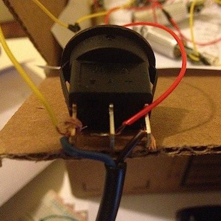
Nine 5mW laser modules are wired in parallel and breadboarded before soldering. I also added an optional power button to the circuit, to be able to turn the lasers ON and OFF.
Step 5: Arduino Circuit Wiring
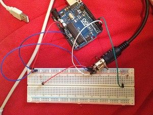
Wire a MIDI jack according to the pinout: Pin 2 – Ground, Pin 4 – 5V (through 220Ω resistor), Pin 5 – Tx. Label everything, it will be vital later. Breadboard the photocells/resistors circuit according to the schematic in Step 3. Solder after testing.
Step 6: MIDI Interface and Software
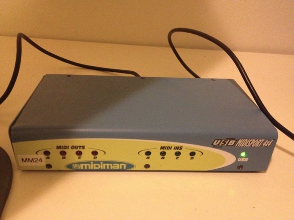
After assembling the Arduino circuit, you need to be able to send MIDI commands to the laptop. In order to do so I used a MIDIsport 4×4 interface (simply because I got it for free). MIDI cable runs from the MIDI jack (Step 5) to the MIDIsport’s Port A, and from there to the laptop running MuLab software.
Read more: Arduino Laser Harp
- How does the laser harp detect notes?
Each laser beam strikes a photocell; when a beam is interrupted the photocell voltage changes and the Arduino sends a MIDI Note On message. - Can I use the Arduino to send MIDI to my laptop?
Yes, the Arduino sends MIDI through a DIN cable to a MIDI interface which connects to the laptop running MIDI software. - What power supply is used for the lasers?
A 5V power supply is used for the laser modules (shown as two AA batteries in the schematic but the build used a 5V supply). - Does the project require woodworking for the enclosure?
Yes, an enclosure was built using pine, MDF, and plywood, but the enclosure design is optional and up to the builder. - What safety precautions are recommended?
Never look directly into the lasers and avoid using laser modules stronger than 5mW. - How are the laser modules wired?
Nine 5mW laser modules are wired in parallel and breadboarded before soldering, with an optional power button. - What resistors are used with the photocells?
Each photocell is wired in series with a 4.7K Ω resistor as a voltage divider. - Do I need a proto shield for the Arduino?
A bare Arduino Proto Shield was used to solder all wires instead of inserting them directly into the Arduino.