Introduction
This guide provides a concise overview of initiating Arduino microprocessor programming through the Arduino Integrated Development Environment (IDE). While these instructions cater specifically to the Arduino Nano board utilizing the ATmega328 microprocessor, a similar process should be applicable to various Arduino boards.
Please note that this guide does not serve as a comprehensive introduction to Arduino or programming for Arduino devices. For more extensive insights into the Arduino microprocessor board family, refer to arduino.cc. The website offers detailed tutorials for specific projects on the tutorials page, and numerous other online resources are available for beginners and tutorials to aid in getting started.
Requirements
Compiling and Uploading
Connect your Arduino to your computer using the USB cable. Upon connection, one of the LEDs on the board, typically labeled “Power,” should illuminate. After a brief moment, the adjacent LED should commence blinking. It’s essential to note that for this sketch, your Arduino doesn’t need to be placed in a breadboard (in fact, I advise against it for now), and there’s no requirement for any external devices to be attached. Due to conducting pins, it’s recommended to avoid placing your board directly on a metal surface. However, apart from this precaution, you should be good to go. Personally, I prefer to let it rest suspended in the air at the end of the short USB cable connected to my laptop.
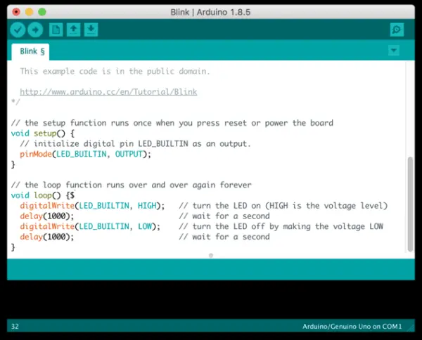
The initial step involves compiling the sketch and checking for errors. Begin by selecting the appropriate board via “Tools : Board” (this is a one-time setup). We’ll be using the Arduino Nano. Next, compile the sketch by pressing the left button on the sketch toolbar. This button, adorned with a checkmark icon and labeled “Verify,” essentially performs the compilation. Although the board doesn’t necessarily need to be connected at this stage, you must select the board beforehand. Review the console output at the bottom of the sketch for any displayed errors. Any text highlighted in red indicates an error that requires rectification before proceeding. Typically, the first sketch shouldn’t have any errors, but as you begin making alterations (which is encouraged!), mistakes may occur. If you’re familiar with writing in C or C++, you shouldn’t encounter significant issues. However, if you’re accustomed to Python, note that the syntax here bears a resemblance, albeit with the caveat that spacing doesn’t hold significance. Nevertheless, each command must conclude with a semi-colon. Additionally, the console provides useful details regarding the program memory and dynamic memory your sketch utilizes. Given that dynamic memory is limited to 2k, it can deplete rapidly.
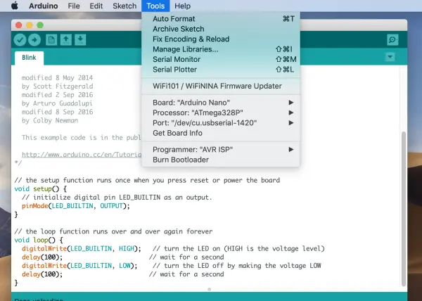
To upload the compiled sketch onto the board, you’ll need to locate the board on the system and select a bootloader. Go to “Tools : Processor” and choose ATmega328P, as this tends to be compatible with most purchased boards. However, occasionally, you might encounter a board with an older bootloader. If you encounter download errors, try switching to the “ATmega328P (Old Bootloader)” option. Typically, one of these two selections should work. Additionally, you’ll need to identify the serial connection to the board. Navigate to “Tools : Port” where you’ll find an entry corresponding to your Arduino. This entry might have a unique name (e.g., /dev/usb.serial-1420 on Mac or something like COM1 on Windows). Each time you plug in your board, it acquires a different USB-serial connection, so you may need to reselect this whenever starting a new session. If there are multiple choices, try selecting one initially and switch to the other if it doesn’t function.
After selecting these parameters, you should be ready to upload your compiled sketch onto the board. Click the “Upload” button in the toolbar (depicted as an arrow) and carefully review the console output. If anything appears in red, the upload didn’t succeed. If that happens, attempt using a different port first. If that fails, switch to the other ATmega328P bootloader. The upload command also recompiles your sketch in case there were any modifications, allowing you to simply press the upload button again to retry. If there were no errors, your Arduino Nano should now be running your sketch.
If you’re unable to locate a serial port or the Port menu item is grayed out, it’s likely that your computer lacks a driver for the CH340 USB interface chip utilized in these Arduino clones. This issue is more prevalent in older operating systems. Although most recent operating systems should have the driver pre-installed, this isn’t always the case. Several websites offer instructions for installing the driver, but one reliable source with instructional videos is available at Sparkfun: How to install CH340 Drivers.
Verification
It’s quite easy to deceive yourself when dealing with embedded systems and microprocessors. Specifically, the Arduino Nano arrives preloaded with the same Blink program that you’ve just uploaded, making it challenging to ascertain whether your program is genuinely running. To verify its execution, try modifying the blink duration by altering the argument within the delay functions.
 digitalWrite(LED_BUILTIN, HIGH);   // turn the LED on (HIGH is the voltage level)
  delay(1000);                       // wait for a second
  digitalWrite(LED_BUILTIN, LOW);    // turn the LED off by making the voltage LOW
  delay(1000);                       // wait for a second
The initial digitalWrite command activates the LED, while the second one deactivates it. The delay functions determine the duration (in milliseconds), typically set for one second on and one second off by default. Adjust the numerical values, for instance, to 500, to accelerate the LED blinking. Compile and upload the sketch, then confirm that the LED now blinks at a quicker pace. Everything enclosed within the loop() section runs continuously on the microprocessor. You can introduce various commands within this loop() section, and they will be executed accordingly. For instance, you could replicate this sequence of writing HI/delay/writing LO/delay multiple times, applying distinct delays each time to create diverse flashing patterns.
If successful, congratulations! You’ve validated that communication with your board and sketch uploads are functioning correctly. It’s advisable to verify basic code like this for any new board, as there’s a chance of encountering boards that are non-operational upon arrival.
Note: The only method to power off your Arduino is by disconnecting it from the USB port. You can safely do this at any time. Once programmed, the Arduino’s program memory retains the last uploaded sketch and will execute it upon powering up again.
Troubleshooting
If errors occur during the compilation phase, carefully review your code for any syntax errors, as these issues are generally unrelated to the board itself. Typically, syntax errors within your code are the primary cause. In some instances, memory depletion may occur, especially in more complex sketches or with extensive use of strings.
For errors encountered during the upload stage, the probable causes are usually related to selecting an incorrect processor or an incorrect port. Adjusting these settings may resolve the issue. If these changes do not rectify the problem, there might be an issue with the board. Seek assistance, as troubleshooting further might exceed your current skill level. In case you encounter a scenario where a previously functional board refuses to be programmed or the program appears unresponsive, you can perform a forced reset by pressing and holding the button on the Nano board for a few seconds. This action is rarely necessary, but I’ve occasionally found it helpful.