Summary of Arduino hardware hacking: Part 3
This article details Part 3 of an Arduino Simon game project, focusing on adding sound capabilities. It explains how to integrate a piezo element or salvaged PC speaker using "bit banging" to generate tones that mirror LED flashes. The guide covers hardware wiring to digital pin 9, circuit diagram interpretation, and provides C++ code snippets for generating specific musical notes (C, D, E) within the existing game logic to enhance playability.
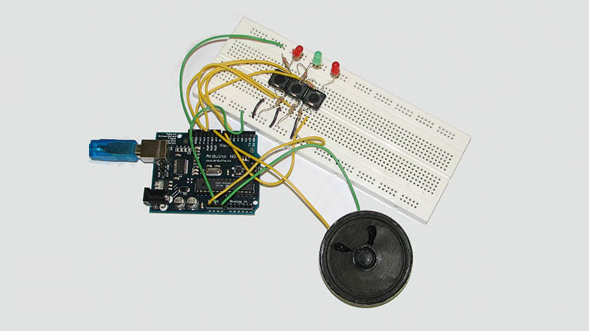
Parts used in the Arduino Simon Game with Sound:
- Arduino board
- Breadboard
- Three buttons
- Three LEDs
- Piezo element or small speaker from old PC case
- Resistors (1 kilohms)
- Wires for connections
In our previous two tutorials (see here and here), we created a Simon-type game using the Arduino, a hardware platform for simple, and not so simple, electronics projects.
We placed three buttons and three LEDs on to something called a breadboard, and wrote a small program that would send a random sequence to the LEDs, which the player would then need to replicate by pressing the buttons in the same order. Each time you got the sequence correct, the sequence would be extended by one and repeated. The further into the random sequence you got, the higher you scored.
In this, part three, we’re going to build on what we already created and add another important feature – sound! So, get the hardware out, make some coffee, and prepare for some hardware hacking fun…
Adding sound to our project is actually very easy, and it has a dramatic effect on the playability of the game. If you purchased a starter pack of components with your Arduino kit, there’s a good chance that the kit included some kind if Piezo element. These are usually small, black and circular (about the same size as the average coat button), with a small hole in the top. They can be used to generate sound, as well simple sound capture, which is why they’re usually included in starter kits.
If you don’t have a Piezo element to hand, don’t worry – neither did we. Rather than go out and buy one, we cannibalised an old PC case and removed the speaker, soldering two wires to the connection points on the edge of the magnet that drives the speaker (you might even be able to remove the speaker with the wires attached). Any small speaker should do, and you’d be surprised how many electronic components include one. If you have something broken lying around, take a look inside.
We got our speaker for free, but they are available for next to nothing from your local hardware store.
Sound and vision
When the speaker is connected to the Arduino, we’re going to use sound to mirror the sequence of the LEDs, so that each flash of light is accompanied by a note. In this way, the random sequence of LEDs that light up will now be generating a melody at the same time, and all the player has to do is imitate the LED sequence/melody on the three buttons.
Even if you’re not interested in the Simon game we’re creating, you can use what you learn here without embedding it within a bigger project. Sound on the Arduino will just work, and there all kinds of applications we can think of where sound would be a useful addition.
Sound generation
There are many different ways to generate sound with the Arduino, all varying in complexity. We’re going to use the absolute simplest, a method that’s crudely known as ‘bit banging’. Bit banging will enable us to generate notes of different pitch, but it won’t give us much else – just a raw beep of a certain duration. Don’t be put off – the sound is actually quite pleasant, and will be familiar to anyone who grew up in the 1980s. Our sound will be very similar to that generated by the original Simon game and many other electronic devices, including the typical ‘beep’ you get when you turn your computer on. Presumably this is because the method we’ve chosen has been the simplest and cheapest way to generate sound for some time, and you don’t need any audio-specific hardware other than the speaker.
If you’re interested in sound and want to try something a little more ambitious, other sound generation methods can use a digital/analogue converter for the recreation of samples and real sound, and there are several Arduino projects that attempt to recreate the various discrete components you find in a synthesizer, including the oscillators, filters and envelopes, as well as tying it all together with MIDI. If you’re interested in any of these applications, the Arduino website has plenty more information.
Beep beep…
But all we want is a beep. To show you how easy it is, attach the positive connection on your speaker to the 9V power connector on the Arduino (you should find small plus and minus signs on the speaker’s circuit board to indicate polarity). Next, connect the negative cable to digital pin 9 on the Arduino, and that’s all the wiring you need. If you’ve still got the Simon-type game from the previous tutorials wired up, these two connections should fit alongside the wires going to and from the LEDs and buttons on the breadboard. We now need to write the code to create a sound.
Like having bits of wire and LEDs lying bare on your desk? So do we – Arduino is great fun!
The basic principle is very similar to switching the LEDs on and off, at least as far as the programming is concerned. That’s why this is called bit bashing. We first set the pin mode of the connector attached to the speaker, then send a HIGH and LOW signal to the same connector, sending a digital signal down the wire to the speaker, resulting in a tiny click as the coil on the speaker jerks briefly in response to the signal. If you were to draw the movement on a piece of paper, you’d see that the speaker had generated a single cycle of a square waveform – a sharp ‘on’ slope with a momentary peak followed by a sharp ‘off’ slope. Now, if we send many more of these small signals to the speaker, generating plenty more square wave cycles, the cumulative effect of the coil and cone jumping backward and forward is that a tone is generated, with the pitch governed by the number of cycles we can fit into a second.
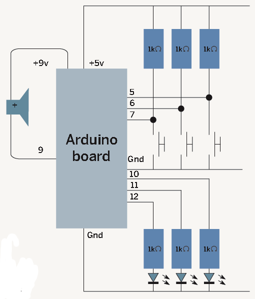
Circuit diagram
One thing that was missing from our previous tutorials was an easier way to explain the layout of the circuit. It’s difficult to describe how everything holds together using text in any project that’s more complex than an LED or two. We had meant to include a circuit diagram to help with this, but ran out of space. Fortunately, a reader has come to our rescue. Stewart Watkiss sent us his own circuit diagram for the project, which we’ve printed here, and added a speaker to reflect the changes in this tutorial.
If you’ve not seen a circuit diagram since you were at school, they’re actually very easy to understand, and make the job of constructing the circuit much easier. You can see the various output connections from the Arduino board, and how these are attached to the resistors (shown with their resistance values of 1 kilohms). The other symbols are for the switches and LEDs. Switches are shown as a momentary break in the circuit, while the LEDs are the inverted triangles with the arrows showing the light emission moving away from the element. The only other device is the speaker, which should be easy enough to spot.
… beep beep, yeah!
Enough theory – let’s make some noise. Open a new Arduino project with the Arduino IDE (or a text editor if you prefer), and type the following at the top of the file:
#define note_len 200000
int speakerOut = 9;
void setup() {
  pinMode(speakerOut, OUTPUT);
}
These lines are telling the Arduino hardware exactly how we’re going to use the pins on the board. We now need to add the code to generate the sound. To do that, just add the following function:
void playTone(int note) {
  long elapsed_time = 0;
  while (elapsed_time  < note_len) {
      digitalWrite(speakerOut,HIGH);
      delayMicroseconds(note / 2);
      digitalWrite(speakerOut, LOW);
      delayMicroseconds(note / 2);
      elapsed_time += (note);
   }
}
In the ‘while’ loop, the digital pulse is sent to the speaker using the digitalWrite functions – HIGH for on, and LOW for off. There is a delay after each digitalWrite implemented using the delayMicroseconds function. As its name implies, this pauses the execution of the program for the number of microseconds indicated by the number between the brackets. In our case, we’ve assigned this number to a variable called ‘note’ because it’s the value of this delay that creates pitch in the sound. The less the delay, the faster the pulse will be sent to the speaker and the higher the pitch. We then add the length of all these delays together to the elapsed_time variable so that we can work out how long the sound has been playing, and when the note has been playing for the duration held in note_len we exit the while loop.
To create a sound, we now move to the final function – loop. In the loop function that the Arduino constantly runs through, we can call the playTone function to create the sound:
void loop() {
   playTone (3830);
}
Put it into the game
Now that we’ve run over the basics of how to generate sound with the Arduino and a cheap speaker, we need to apply what we’ve learned to the game we created. The first step is to copy the playTone function from our previous example into the game source code. We’re going to use this in exactly the same way, calling the function when we want to create a sound.
To go along with the new function, we also need to add the same pinMode line to the setup function, as well as make sure the note_len and speakerOut definitions are copied to the top of the file. We’re also going to add some more #define statements for the notes that various delays in the playTone function will play. Doing this helps us to avoid using the raw numbers for the delay value as we did in the loop() function, and as we’ve only got three buttons, we only need three tones:
#define  play_c     3830
#define  play_d     3400
#define  play_e     3038
We took the delay values from the Arduino website, where someone has already worked out which delays produce which note. We can now use the fixed variables play_c, play_d and play_e as the arguments in our playTone function to generate the correct tone we want, and this is what we need to add next – create a sound when the corresponding LED is lit up, and we can do this from playSequence – the same function that lights the LEDs. Jumping into the middle of this function, you might remember that we used a case statement that would light the correct LED according to which value was held in the current position of the array. We can simply add the playTone command in each case to play a tone when the LED is lit:
For more detail: Arduino hardware hacking: Part 3
- How can I generate sound if I do not have a Piezo element?
You can cannibalize an old PC case to remove a small speaker and solder two wires to the connection points on the magnet. - What is the simplest method to generate sound with an Arduino mentioned in the text?
The article describes a method crudely known as bit banging which generates raw beeps of different pitches. - Which digital pin should the negative cable of the speaker be connected to?
The negative cable should be connected to digital pin 9 on the Arduino. - How does the delay value affect the pitch of the generated sound?
A smaller delay results in faster pulses being sent to the speaker, creating a higher pitch. - What function is used to pause program execution for microseconds to control tone duration?
The delayMicroseconds function is used to pause execution based on the number of microseconds indicated. - Can I use the sound generation techniques without embedding them in the Simon game?
Yes, sound on the Arduino will work independently and has many other applications beyond this specific project. - What are the three defined note variables added to the code for the game?
The code defines play_c, play_d, and play_e to correspond to the three buttons. - Where did the author obtain the delay values for the specific musical notes?
The delay values were taken from the Arduino website where someone had already calculated them.