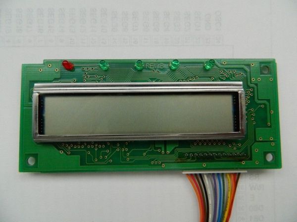
I acquired an old fax machine that looked like a ripe source of parts, like steppers, IR sensors, micro switches and things. As it turned out, it was. It also had a nice looking 2 x 16 character LCD. However, after taking everything apart, I found the LCD only had 13 pins instead of the more common 10, 14 or 16 pins. They were not labeled, so that’s where the investigation came in. After an exhaustive search online, I did not find anything but questions from a few other people who wanted to know the same thing I did. How in tarnation do you hook this thing up so it can be used? It’s too good to throw away! I had to ring out the card to find where the pins registered on the chip.
The general process I planned was to trace out the signals from connector pins to their corresponding pins on the LCD controller chip. By doing this, I should be able to figure out how to connect the display to use it.
Step 1: Getting ready
First things first. The LCD was a standard display driven by a Hitachi 44780 chip, so I had somewhere to begin. I located a copy of the datasheet for that chip to use as my guide to determine which pins on the chip did what.
Using the datasheet, I was able to determine which pin was #1 and how they were labeled.
The next step was to take a couple of photos of the LCD (front and back) to blow up to help in tracing out the traces on the PCB. The board was small and the traces were tiny and close together, so it was hard to do some simple visual analysis of which traces went where. So easy to get confised! Taking photos and blowing them up so I could see them 8.5 x 11 was a tremendous help.
The next step was to get out my digital voltmeter and start testing between points to confirm what I thought I had found by following the traces. Using the photos, I followed each trace from the connector pins to the chip, or wherever they went. I used the 44780 datasheet to identify what pins on the chip I had traced to. Since I wasn’t planning on addressing this chip by individual segments, I figured I could ignore the SEG and COM pins and focus on the DB, RS, R/W, E, clock and voltage pins.
Tools:
Digital camera
Printer
Digital voltmeter
Datasheet
Patience
Step 2: Visual analysis
I printed out the photo of the back side of the board on regular letter sized paper to make it easier to trace out. With the larger version, I was able to trace out a couple of things right off. First, Pin 1 seemed to be connected to a large area that looked like ground plane. In testing it out and testing it to Pin 23 of the HD44780 chip (GND), I confirmed it was most likely the ground pin.
Pins 2 – 9 looked harder to follow, so I worked my way back in from Pin 13. Pin 13 was traced to Pin 46 on the chip, which was DB7. Pins 12, 11 and 10 traced to pins 45, 44 and 43, respectively. Things were looking good now. Using the meter to test continuity, I checked to see if pins 6, 7, 8 and 9 corresponded to the remaining DB pins, and they did. Now I know which inputs provide to which display pins. Now to crack connector pins 2 – 9.
Pin 2 was smelling like it might be power, so I checked between pin 2 on the connector and pin 33 on the chip, and sure enough, it tested true. Now I just tested by putting one probe on a connector lead and the other on an unidentified necessary pin on the chip, and was able to figure out the rest. I marked each connection on my printout of the board for easier management later. Here is the final tally:
Connector HD44780
1 G
2 Vcc
3 V5
4 RS
5 E
6 DB0
7 DB1
8 DB2
9 DB3
10 DB4
11 DB5
12 DB6
13 DB7
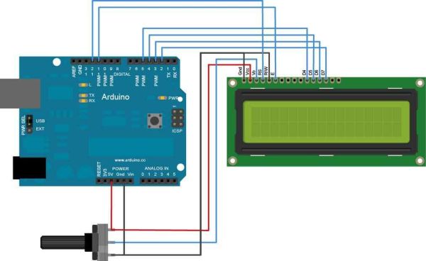
That leaves a couple of the normally used pins not used, like RW and those used to manage backlight. I figured the backlight was not used in the fax machine, so no worries there. Since it is often done with the R/W pin when using this type of display, perhaps R/W was already tied to ground to give max display contrast, and that’s why it was not connected to its own pin on the connector. Since I had nothing to lose, I decided to try hooking things up to an Arduino to test using the pins I had.
[box color=”#985D00″ bg=”#FFF8CB” font=”verdana” fontsize=”14 ” radius=”20 ” border=”#985D12″ float=”right” head=”Major Components in Project” headbg=”#FFEB70″ headcolor=”#985D00″]Digital camera
Printer
Digital voltmeter
Datasheet
Patience[/box]
For more detail: Salvaging an LCD from a fax machine using an Arduino