Summary of Arduino Guitar Pedal using arduino
The Arduino Guitar Pedal is a customizable digital multi-effect pedal featuring a built-in preamp and active mixer. It allows users to blend clean guitar signals with various effects, controlled by a rotary switch offering six discrete steps. The project relies on an Arduino Uno for digital signal processing, enabling endless customization through programming.
Parts used in the Arduino Guitar Pedal:
- Arduino Uno REV 3
- Make MakerShield Prototyping Kit
- 100K-Ohm Linear-Taper Potentiometer (x3)
- 2-Pole, 6-Position Rotary Switch
- Hexagonal Control Knob with Aluminum Insert (x4)
- TL082/TL082CP Wide Dual JFET Input Op Amp
- 1/4 Stereo Panel-Mount Audio Jack (x2)
- 1uF 63v capacitor (x4)
- 47uF 16v capacitor (x2)
- 100pF 50V Ceramic Disc Capacitor
- 0.082µf 100V Mylar Capacitor
- 5pf 50V Ceramic Disc Capacitor
- 10K Ohm Carbon Film Resistor (x6)
- 1M Ohm Carbon Film Resistor (x2)
- 390K Ohm Carbon Film Resistor
- 1.5K Ohm Carbon Film Resistor
- 510K Ohm Carbon Film Resistor
- 330K Ohm Carbon Film Resistor
- 4.7K Ohm Carbon Film Resistor
- 12K Ohm Carbon Film Resistor
- 1.2K Ohm Carbon Film Resistor
- 1K Ohm Carbon Film Resistor
- 100K Ohm Carbon Film Resistor (x2)
- 22K Ohm Carbon Film Resistor
- 33K Ohm Carbon Film Resistor
- 47K Ohm Carbon Film Resistor
- 68K Ohm Carbon Film Resistor
- Heavy-Duty 9V Snap Connectors
- UL-Recognized Hookup Wire
- Enercell Alkaline 9 Volt Battery
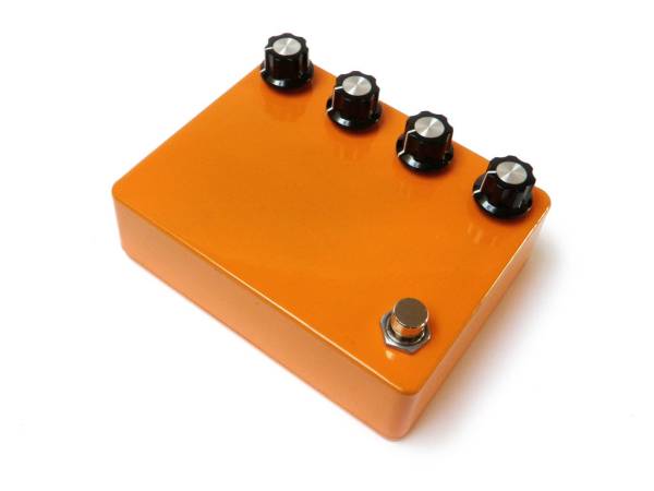
- Box BB Size Orange Powder Coat
- DPDT Stomp switch
- Rubber mat
- Cork mat
The Arduino Guitar Pedal is a digital multi-effect pedal based upon the Lo-Fi Arduino Guitar Pedal originally posted by Kyle McDonald. I made a few modifications to his original design. The most noticeable changes are the built-in preamp, and the active mixer stage which lets you combine the clean signal with the effects signal. I also added a sturdier case, foot switch, and rotary switch to have 6 discreet steps between the different effects.
The cool thing about this pedal is that it can be endlessly customized. If you don’t like one of the effects, simply program another one. In this way, this pedal’s potential is largely dependent upon your skills and imagination as a programmer.
Step 1: Go get stuff
You will need:
(x1) Arduino Uno REV 3 (Radioshack #276-128)
(x1) Make MakerShield Prototyping Kit (Radioshack #276-138)
(x3) 100K-Ohm Linear-Taper Potentiometer (Radioshack #271-092)
(x1) 2-Pole, 6-Position Rotary Switch (Radioshack #275-1386)
(x4) Hexagonal Control Knob with Aluminum Insert (Radioshack #274-415)
(x1) TL082/TL082CP Wide Dual JFET Input Op Amp (8-Pin DIP) (Radioshack #276-1715)
(x2) 1/4″ Stereo Panel-Mount Audio Jack (Radioshack #274-312)
(x4) 1uF 63v capacitor (Radioshack #55047191)
(x2) 47uF 16v capacitor (Radioshack #55047280)
(x1) 100pF 50V 10% Hi-Q Ceramic Disc Capacitor (Radioshack #272-123)
(x1) 0.082µf 100V Mylar Capacitor (Radioshack #55046837)
(x1) 5pf 50V Ceramic Disc Capacitor (Radioshack #55047529)
(x6) 10K Ohm 1/4-Watt Carbon Film Resistor (Radioshack #271-1335)
(x2) 1M Ohm 1/4-Watt Carbon Film Resistor (Radioshack #271-1356)
(x1) 390K Ohm 1/4-Watt Carbon Film Resistor (Radioshack #55049555)
(x1) 1.5K Ohm 1/4W 5% Carbon Film Resistor (Radioshack #271-1120)
(x1) 510K Ohm 1/4W 5% Carbon Film Resistor (Radioshack #55049227)
(x1) 330K Ohm 1/4W 5% Carbon Film Resistor (Radioshack #44049468)
(x1) 4.7K Ohm 1/4-Watt Carbon Film Resistor (Radioshack #271-1330)
(x1) 12K Ohm 1/4-Watt Carbon Film Resistor (Radioshack #55049436)
(x1) 1.2K Ohm 1/4-Watt Carbon Film Resistor (Radioshack #55049409)
(x1) 1K Ohm 1/4-Watt Carbon Film Resistor (Radioshack #271-1321)
(x2) 100K Ohm 1/4-Watt Carbon Film Resistor (Radioshack #271-1347)
(x1) 22K Ohm 1/4-Watt Carbon Film Resistor (Radioshack #271-1339)
(x1) 33K Ohm 1/4-Watt Carbon Film Resistor (Radioshack #55048044)
(x1) 47K Ohm 1/4-Watt Carbon Film Resistor (Radioshack #271-1342)
(x1) 68K Ohm 1/4-Watt Carbon Film Resistor (Radioshack #55049451)
(x1) Heavy-Duty 9V Snap Connectors (Radioshack #270-324)
(x1) 90-Ft. UL-Recognized Hookup Wire (Radioshack #278-1221)
(x1) Enercell® Alkaline 9 Volt Battery (Radioshack #25-853)
(x1) Box ‘BB’ Size Orange Powder Coat (Small Bear #0301G)
(x1) DPDT Stomp switch (Small Bear #0203)
(x1) 1/8″ x 6″ x 6″ rubber mat
(x1) 1/8″ x 12″ x 12″ cork mat
Step 2: Header breakdown
Break the male header strip down to fit properly in the Maker Shield kit.
An easy way to do this is to insert the end of the strip into each of the Arduino sockets and then snap off the excess pins. You will end up with 4 strips of proper size
Step 3: Solder
Step 8: Build the circuit
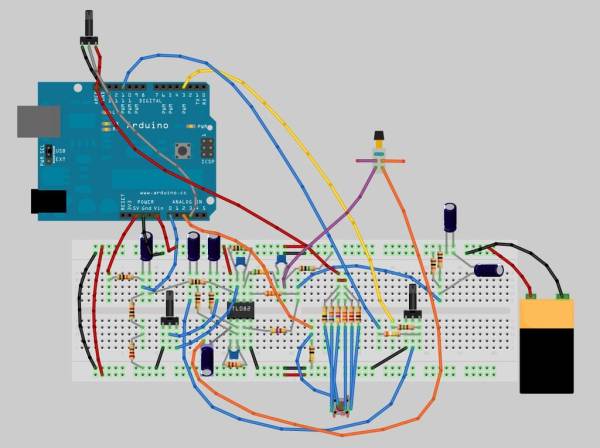
Start to build the circuit as pictured in the schematic. To see the schematic larger, click the little “i” in the upper right-hand corner of the image.
For now, while building the circuit, do not worry about the potentiometers, rotary switch, bypass switch, and input jacks.
To better understand what you are doing, this circuit consists of a few different parts:
Preamp
The preamp uses one of the two op amps packaged in the TL082. The preamp is both boosting the guitar signal to line level and inverting the signal. When it comes out of the op amp the signal is split between the Arduino input and the “clean” volume knob for the mixer.
Arduino Input
The input for the Arduino was copied from Kyle’s input circuit. It is basically taking the audio signal from the guitar and constraining it to roughly 1.2V, because the aref voltage within the Arduino has been configured to look for an audio signal in this range. The signal is then being sent to analog pin 0 on the Arduino. From here, the Arduino is then converting this to a digital signal using its built in ADC. This is a processor intensive activity and where most of the Arduino’s resources are being allocated.
You can get a faster conversion rate and do more multiprocessing of the audio signal using timer interrupts. To learn more about that, check out this page on Arduino Real-Time Audio Processing.
Arduino
The Arduino is where all of the fancy-shmancy digital signal processing is happening. I’ll explain a bit more about the code later. For now, in relation to the hardware, what you need to know is that there is both a 100k potentiometer connected to analog pin 3 and a 6-position rotary switch connected to analog pin 2.
The 6-position rotary switch is functioning in a similar way to a potentiometer, but rather than sweeping through a resistance range, each pin has a discrete resistance associated with it. As you select different pins, voltage dividers of different values are created.
Since the analog reference voltage had to be remapped to handle the incoming audio signal, it is important to use aref as the voltage source, as opposed to the standard 5V for both the rotary switch and the potentiometer.
Arduino Output
The Arduino output is only loosely based on Kyle’s circuit. The part I kept was the weighted pin approach to get the Arduino to output 10-bit audio using only 2 pins. I stuck with his suggested weighted resistor ratings of 1.5K as the 8-bit value and 390K as the added 2-bit value (which is basically 1.5K x 256). From there I scrapped the rest. His output stage components were unnecessary because the audio was not going to an output, but rather to the new audio mixer stage.
Mixer Output
The effects output from the Arduino goes to a 100K pot connected to the audio mixer op amp. This pot is then used in conjunction with the clean signal coming from the other 100K potentiometer to mix the volume of the two signals together in the op amp.
The second op amp on the TL082 is both mixing the audio signals together, and inverting the signal once again to get it back in phase with the original guitar signal. From here the signal goes through a 1uF DC blocking capacitor and finally to the output jack.
Bypass Switch
The bypass switch toggles between the effects circuit and the output jack. In other words, it either routes the incoming audio to the TL082 and the Arduino, or skips all of this entirely and sends the input straight to the output jack without any altering. In essence, it bypasses the effects (and hence, is a bypass switch).
I have included the Fritzing file for this circuit if you want to look at it closer. The breadboard view and schematic view should be relatively accurate. However, the PCB view has not been touched and probably will not work at all. This file does not include the input and output jacks.
For more detail: Arduino Guitar Pedal
- What are the main modifications made to the original design?
The most noticeable changes include a built-in preamp and an active mixer stage that combines the clean signal with the effects signal. - How many discreet steps does the rotary switch provide?
The rotary switch provides 6 discreet steps between the different effects. - Can the effects on this pedal be customized?
Yes, the pedal can be endlessly customized because if you do not like one of the effects, you can simply program another one. - How is the audio signal handled by the Arduino input circuit?
The circuit constrains the audio signal to roughly 1.2V to match the configured aref voltage before sending it to analog pin 0 for conversion. - Does the bypass switch alter the audio signal?
No, the bypass switch routes the incoming audio straight to the output jack without any altering when activated. - What voltage source should be used for the rotary switch and potentiometer?
You must use aref as the voltage source instead of the standard 5V because the analog reference voltage was remapped to handle the incoming audio signal. - How does the Arduino output generate 10-bit audio?
The output uses a weighted pin approach with two pins, utilizing specific resistor ratings to achieve 10-bit audio. - What happens to the signal after it passes through the second op amp?
The signal goes through a 1uF DC blocking capacitor and finally to the output jack after being mixed and inverted back to phase.