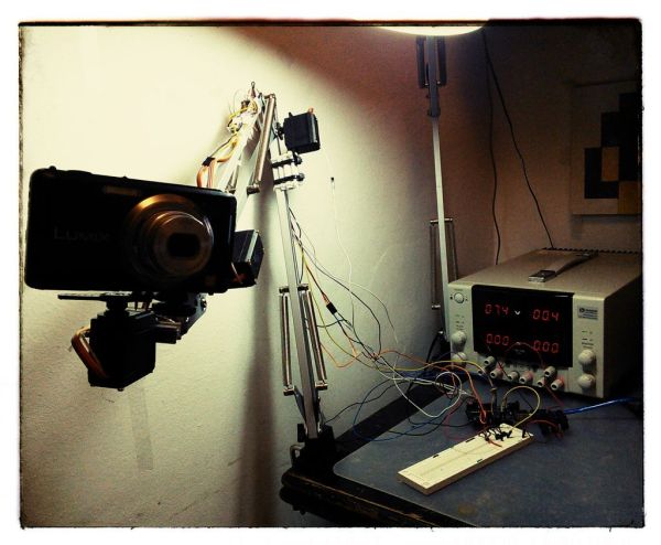
Summary of Robot arm from a desk lamp (IKEA Tertial hack)
This project transforms a standard IKEA Tertial lamp into a motion-capturing robotic arm that holds a camera. By modifying servos for analog feedback and mounting them directly onto the lamp's structure, the device records movements to replay them without programming. It features three degrees of freedom: two for arm articulation and one dedicated to rotating the camera mount, allowing users to create videos or photos hands-free in a lab setting.
Parts used in the IKEA Tertial Robotic Camera Arm:
- IKEA Tertial lamp
- MG995 servos (modified for analog feedback)
- Standard servos (for comparison or additional use)
- Camera with 3/8" mounting nut
- Servo arms and nuts
- Nuts and small blocks/profiles for camera adapter
- Bolts for servo center of rotation replacement
- Spacers and zip ties for securing servo bodies
- Tape for holding servo tops during modification
- Soldering equipment and wires
- CAD software for modeling
This project answers to a need I had: a third hand that holds a camera while I perform a test and takes photos/videos (useful when you’re stuck at the lab late at night, and suddenly need a photographer).
The downside to a robotic arm was obvious – It needs to be programmed, and it is the last thing you want to do when you need to make a video. So I made it motion capturing device as well…
Motion capturing and playing device – you “teach” the arm what it should do, and it repeats the movement! (no programming or computer needed).
For long time I wanted to transform standard IKEA Tertial lamp (here) into a functional robotic hand, I wanted to make it easy, without any manufactured parts, and to control as many degrees of freedom (DOF) as possible.
After modeling the lamp using my favorite CAD software, I realized the standard servos, placed in the right places can (to some extent) work.
Step 1: Stripping and modeling IKEA Tertial lamp
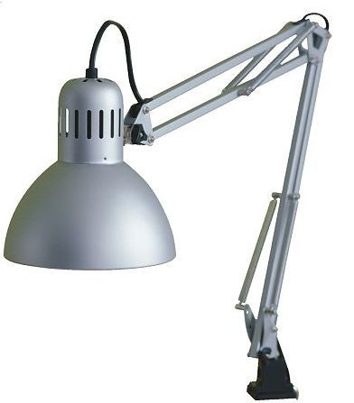
First step is, of course, to get a Tertial lamp, should be quite easy to get here, and remove the power cord (must be cut), dismantle the lampshade (But leave it’s connector !) and remove the springs for future use.
Step 2: Hacking servos for analog feedback
In purpose to get feedback from the servos, they should be capable to give feedback (analog), ready made analog servos can be found at Adafruit, or can be manually made as described here:
( I used cheap MG995 ), after some ruined servos I managed to figure the right steps:
- Pick the servo…
- USE TAPE (see image) to hold the top (the side near the power output) otherwise the transmission might fall apart
- Remove 4 cross bolts from the bottom.
- Take the PCB out gently, and position in your soldering stand
- Solder wire to the middle connection of the servo’s potentiometer
- Assemble all back to have an “Analog feedback” servo.
repeat 3 times for all servos needed for the project.
Step 3: Camera adapter
Connection of the camera to the arm should be easy release and enable full rotation,
Camera to servo steps:
- Pick one servo.
- Pick some nuts and arms (that come with the servo)
- Get a nut to mount the camera (any 3/8″ nut will do).
- Build an arm that fit your camera,
- You’re done !
Now, you need to connect the servo to the arm tip:
- Pick the arm tip part
- Bend the little metal plate to straight line.
- Take any small block/profile and mount to the metal plate.
- Mount the servo to the same block/profile
- You’re done !
Step 4: Connecting motors to the arm
The arm should be actuated with two servos (the third is used for the camera – see previous step)
Servo 2 (arm end) mounting steps:
- Dismantle the triangular plate from the arm tip.
- Drill few holes to enable mounting of the servo arm to the plate.
- Mount the servo arm to the plate
- Assemble the plate back to the arm
- REPLACE THE UPPER BOLT, with a bolt the goes directly into the servo center of rotation. (see images)
- Tighten the servo body to the bar (I used spacers and zip ties – improvise!
Servo 3 (middle) mounting steps:
- Dismantle the trapeze plate from the arm.
- Drill few holes to enable mounting of the servo arm to the plate.
- Mount the servo arm to the plate
- Assemble the plate back to the arm
- REPLACE THE UPPER BOLT, with a bolt the goes directly into the servo center of rotation. (see images)
- Tighten the servo body to the bar (I used spacers and zip ties – i
For more detail: Robot arm from a desk lamp (IKEA Tertial hack)
- How does the motion capturing feature work?
You teach the arm what to do by moving it manually, and it repeats the movement without needing programming or a computer. - What is the main advantage of this project over a standard robotic arm?
This device requires no programming, making it ideal when you need to quickly make a video or take photos. - Which specific lamp model is used as the base for this robot?
The project uses the standard IKEA Tertial lamp which is stripped of its power cord and springs. - How are the servos modified to provide analog feedback?
You remove the PCB, solder a wire to the middle connection of the potentiometer, and hold the top with tape to prevent transmission failure. - How many degrees of freedom does the final arm have?
The arm has three degrees of freedom controlled by three servos: two for the arm and one for the camera. - What hardware is required to mount the camera securely?
A 3/8" nut is used to mount the camera, attached to an arm built from servo parts and small blocks. - Can I use ready-made analog servos instead of modifying MG995s?
Yes, ready-made analog servos can be found at Adafruit, though the author successfully modified cheap MG995 servos. - How is the servo body secured to the lamp bar?
The servo body is tightened to the bar using spacers and zip ties or similar improvised methods.