Do you pay too much for your electricity bills?
Do you want to know how much electricity your kettle or heater consumes?
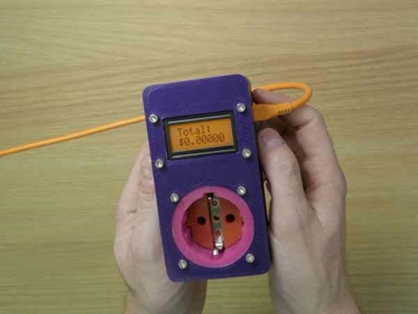
Make your own portable Energy Cost Electrical Meter!
Watch how I found the use of this device.
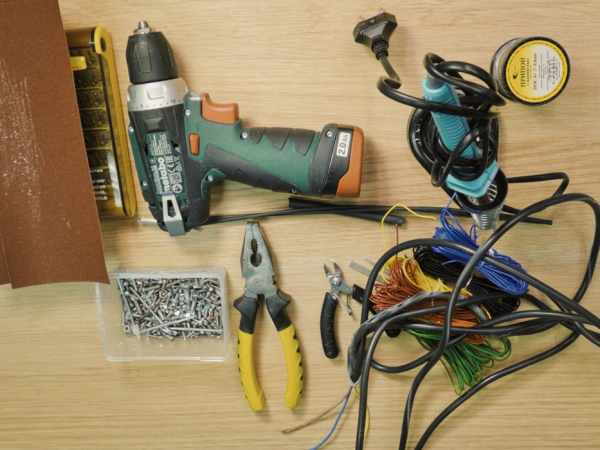
Step 1: Preparation. Tools Screws and Consumables.
You need several things to make this project.
- Home computer with XOD IDE installed.
- 3D printer.
Tools:
- Clippers.
- Screwdriver.
- Pliers.
- Soldering tools.
- Needle file.
Consumables:
- Sandpaper.
- Shrink tubes.
- 14 AWG wires or less for 220V circuit.
- 24 or 26 AWG wires for 5V logic circuit.
Screws:
- Screw M3 (DIN7985 / DIN 84 / DIN 912) 20mm length.
- Screw M3 (DIN7985 / DIN 84 / DIN 912) 10mm length.
- Screw M2 / M2.5 (DIN7981 or other).
- Hex nut M3 (DIN 934/ DIN 985).
Step 2: Preparation. Electronics.
To create the device you need some electronic components. Let’s figure out which ones.
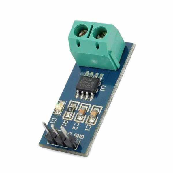
First of all, you need an AC current sensor.
The device can works with a high current, so the sensor should be suitable. On the internet, I found an ACS712 sensor manufactured by Allegro.
1 x 20A range Current Sensor ACS712 Module ~ 9$;
This sensor is analog and measures current using the Hall effect. It uses one wire to transmit the measured value. It may not be very accurate, but I think it’s enough for such a device. The ACS712 sensor can be of three types with different maximum limits of measurement :
- ACS712ELCTR-05B (5 amperes max);
- ACS712ELCTR-20A (20 amperes max);
- ACS712ELCTR-30A (30 amperes max).
You can pick the version you need. I use the 20 amp version. I don’t think the current in my sockets exceeds this value.
You need a controller, to read sensor data and to perform all other calculations.
Of course, I chose Arduino. I think that there is nothing more convenient for such DIY projects. My task isn’t difficult, so I don’t need a fancy board. I bought Arduino Micro.
1 x Arduino Micro ~ 20$;
Arduino is powered by DC voltage up to 12V while I was going to measure AC voltage 220V. Moreover, the ACS sensor should be powered by an exact 5 volts. To solve the problem, I bought the AC to DC converter from 220 to 5 volts.
1 x AC to DC Power Module Supply Input: AC86-265V Output: 5V 1A ~ 7$;
I use this converter to power Arduino and sensor.
To visualize my measurements, l display the amount of money spent on a screen. I use this 8×2 character LCD display.
1 x 0802 LCD 8×2 Character LCD Display Module 5V ~9$;
This is small, compatible with Arduino display. It use own data bus to communicate with the controller. Also, this display has a backlight which can be one of different colors. I got the orange one.
Step 3: Preparation. Sonnectors.
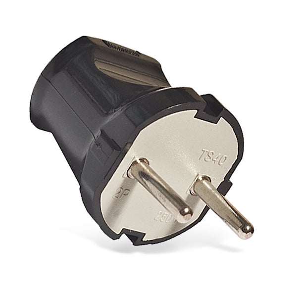
The device should have its own power plug and socket.
It is quite challenging to make a quality and reliable plug connection at home. Also, I wanted the device to be portable and compact without any cords and wires.
I decided to buy some universal sockets and plugs in the hardware store to disassemble them to use any their parts. Connectors that I purchased are F type or as they are called Shuko. This connection is used all over the European Union. There are different connector types, for example, the A or B types are a bit smaller than F and are used in Northen America. The internal dimensions of sockets and external dimensions of plugs are standardized for all connectors of the type.
For more information, you can read about different socket types here.
Disassembling a few sockets, I found that their inside parts can be easily removed. These parts have almost the same mechanical dimensions. I decided to use them.
So, To create own device you need :
- Choose the connection type;
- Find plugs and sockets that you can use, and that can be easily disassembled;
- Remove their inner parts.
I used this socket:
1 x Earthed Female Plug 16A 250V ~ 1$;
And this plug:
1 x Male Plug 16A 250V ~ 0,50$;
Step 4: Preparation. 3D Printing.
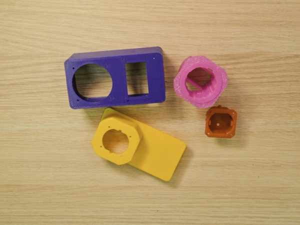
I printed body parts of the device on a 3D printer. I used ABS plastic of different colors.
Here is the list of parts:
- Main body (purple) – 1 piece;
- Back cover (yellow) – 1 piece;
- Socket case (pink) – 1 piece;
- Plug case (red) – 1 piece;
The main body has threading holes to fasten the current sensor and back cover.
The back cover has threading holes to fasten the AC-DC converter and a snap-fit joint to attach Arduino Micro.
All parts have holes for M3 screws to fix the display, plug and socket cases.
Pay attention to the socket case and plug case parts.
The inner surfaces of these parts are pre-modeled specifically for my connectors. For those disassembled connectors from the previous step.
Thus, if you want to make own device and your plug and socket connectors differ from mine, you need to fix or modify the socket case and plug case 3D models.
STL models are in the attachment. If it is necessary, I can attach the source CAD models.
Source: Arduino Energy Cost Electrical Meter Device