Summary of Arduino Drawbot
This article guides beginners in building "The DrawBot," a simple robot using modified 360-degree Parallax servos. It details assembling the chassis from recycled wood and spray paint caps, integrating an Arduino UNO with a breadboard, and wiring the components for power and control. The project emphasizes using household items and provides clear assembly steps for creating a drawing robot capable of moving across paper.
Parts used in the DrawBot:
- Drill with a drill bit
- Screwdriver
- Two spray paint can caps
- Two small screws
- Three rubber bands
- Piece of wood
- Arduino UNO Rev3
- Breadboard
- 9V battery
- 9V connection harness
- Four wires
- A marker
- Two Parallax Servos with 360º modification
- 12 pin connector
- USB cable
- Traction material (e.g., lego tires or electrical tape)
And in my last instructurable I have show the modification of a Parallax servo for a 360º rotation.
So in this one I will show Arduino beginers the use of those 360º rotation servos.
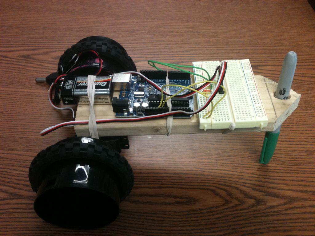
With that in mind we will make our first ROBOT. It will be a simple bot called The DrawBot
For the some of the materials just look around the house and recycle it for the DrawBot to be made
NOTE: The code and the idea was taken from around the internet. And again there are tutorials showing you this simple DrawBot or the 5 Minute Drawbot but they’re not clear enough for the beginner. All the electronics were bought @ RADIOSHACK.
Step 1: Materials
The following will be divided in categories and in no particular order:
Tools:
1. Drill with a drill bit (size depends on the diameter of the marker)
2. Screwdriver to attach the wheels to the servos.
Hardware:
1. (X2) spray paint can caps.
2. (X2) small screws
3. (X3) rubber bands
4. Piece of wood ( size, shape and thickness could be any to fit all the parts)
5. Arduino UNO Rev3
6. Breadboard
7. (9V) battery
8. (9V) connection harness to provide power to the Arduino.
9. (X4) wires for all the connections.
10. A marker ( any color)
11. (X2) Parallax Servos with the 360º MOD
12. 12 pin connector
13. USB cable to prgram the Arduino.
14. Something to add traction to the wheels ( I have use from lego, two rubber tires, but you can use any electrical tape also).
Software:
Arduino software (to upload the code)
Step 2: Step 1
The piece of wood I am using is a 2” wide by 1/4” of thickness.
You can use whatever you got (plastic, metal or even a good piece of cardboard)
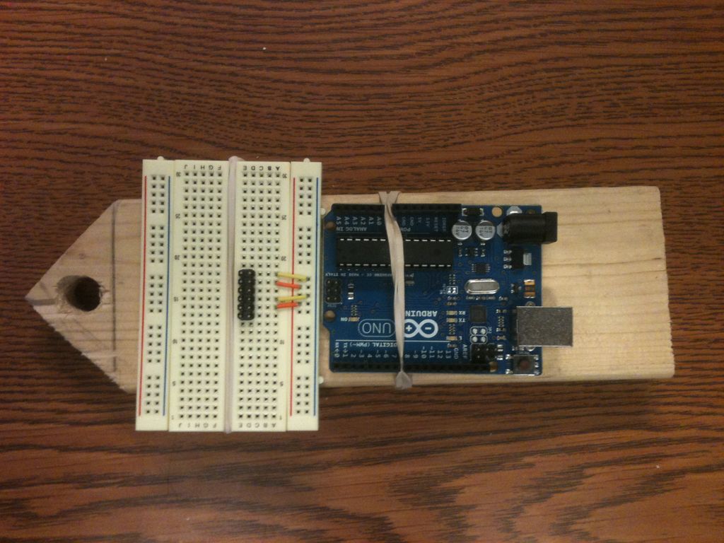
Step 3: Step1 (Bread board)
Step 5: Step 4 (Servos)
Also it is a good practice to write in the back of the base the letters L and R to make the final connections of the servos easy. 😉
Step 6: Step 5 (Wheels)
You don’t need to drill a hole here, the plastic is thin for the screws to go through.
Then add the traction to the caps, it could be electrical tape. ( I have use rubber tires from a lego)
Step 7: Step 6 (First Connection)
Notice that I have use a 12 pin connector to connect the servosto the breadboard.
ORANGE = 5V
YELLOW = GND
Step 8: Step 7 (Second Connection)
Second: Connect the GND connection from the Arduino to the breadboard.
NOTE: (BreadBoard Basics)
When you make a connection from the Arduino to the breadboard it will provide either power or a Pin function connection to the whole row.
- How do I secure the marker in the wood piece?
Drill a hole sized to fit the marker tightly; if loose, add tape around the marker to increase its thickness. - What materials can be used for the robot's base?
You can use any size or shape of wood, plastic, metal, or even a good piece of cardboard. - How are the servos attached to the base?
Attach the two servos directly to the wood base and label the back with L and R for easy connection identification. - How do I create wheels for the servos?
Attach spray paint can caps to the servo arm with two screws and add traction using electrical tape or lego tires. - How is power provided to the servos?
Use a 12 pin connector where orange connects to 5V and yellow connects to GND on the breadboard. - How do I connect the Arduino to the breadboard?
Connect the 5V and GND connections from the Arduino to the breadboard to provide power or Pin function to the whole row. - What software is required to program the robot?
The Arduino software is needed to upload the code to the microcontroller. - Can I find the original code and idea elsewhere?
Yes, the code and idea were taken from around the internet, though this tutorial clarifies previous unclear versions.