This Arduino based digital clock is synchronized by the 60Hz power line. It has a simple and inexpensive common anode 4 digit 7 segment display which shows hours and minutes. It uses a cross over detector to detect when the incoming 60Hz sine wave crosses the zero voltage point and derives a 60 Hz square wave.
Over short time periods the frequency of the incoming sine wave from the power line may vary very slightly due to load, but over long periods of time it averages to 60Hz very precisely. We can take advantage of this to derive a timing source to synchronize our clock.
Step 1: The Circuit Diagram
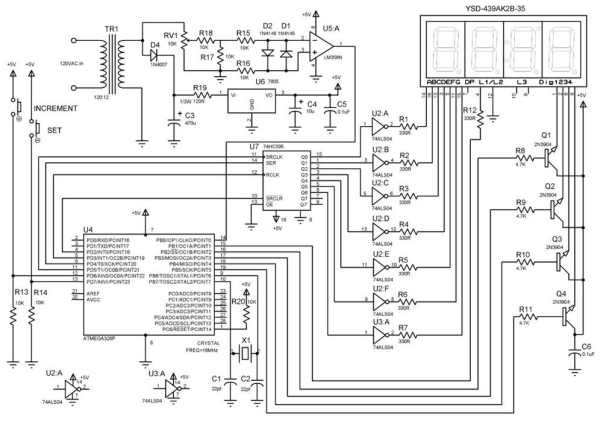
There are two versions of the circuit depending on whether you want to use a transformer with a center tap or one without, in either case the circuit operation is almost identical. For this build I used a wall adapter (no center tap) that outputs 12V AC. I will use this design (Digital Clock1 Circuit Diagram) for the circuit description. Note that it is important to use a wall adapter that outputs 12V AC not 12V DC so that we can tap into the AC sine wave for timing. You could probably also use a transformer that outputs 9V AC, remove R19 and get it to work also, but 12V is very commonly available. This is how the circuit works:
120V AC at 60Hz is converted to 12V AC by transformer TR1. This is fed to diode D4 and rectified so that only +ve voltage is fed to, and smoothed to approximately DC with ripple, by the capacitor C3. The voltage on C3 is fed to the 7805 voltage regulator (U6) via resistor R19. R19 is used to reduce the voltage on C3 which in my case was measured at approximately 15VDC. This can be regulated by the 7805 but with this level of input the 7805 must drop approximately 10VDC and as a result gets quite hot. By using R19 to drop the voltage to about 10VDC we prevent U6 from heating up too much. So this is not an efficient power conversion technique, but it works for our purposes. NOTE: use at least a 1/2W resistor or more here. The circuit draws about 55 ma, so power dissipation in R19 is about 1/3W based on P=I**2*R or P = 55ma x 55ma x 120 ohms = 0.363W. Next U6 outputs pure 5V DC with C4 and C5 on the output to filter any noise on the 5V power line. This 5V DC powers all ICs on the board.
From TR1 we also take a sample of the unfiltered AC signal and feed it into potentiometer RV1 which is used to adjust the level fed to the cross over detector. R18 and R17 form a voltage divider to further reduce the level of AC voltage coming in. Remember this is coming in at 12V AC and we need to reduce it to less than 5 V so that it will work with our cross over detector which is only powered by 5VDC. R15 and R16 provide current limiting while D1 and D2 are intended to prevent overdriving of op-amp U5. In the configuration shown U5’s output on pin 1 will alternate between +5V and 0V each time the incoming sine wave changes from positive to negative. This generates a 60 Hz square wave which is fed to the microcontroller, U4. The program loaded on U4 then uses this 60Hz square wave to increment the clock every minute and hour. How this is done will be discussed in the section on the software program and in the software comments.
U7 the 74HC595 shift register is used because we have a limited number of digital pins on the microprocessor, so it is used to expand the number of outputs. We use 4 digital pins on the microprocessor but can control 7 segments on the display via the 74HC595. This is accomplished by shifting predetermined patterns of bits, stored in the microcontroller, and which represent each digit to be displayed, into the shift register.
The display used here is common anode, so we need to invert the signal levels coming out of the the 74HC595 in order to turn on a segment. When a segment should be turned on the the signal coming out of the 74HC595 output pin will be at +5V, but we need the pin it is feeding on the display to be at 0V in order to turn on that display segment. So to do this we need hex inverters U2 and U3. Unfortunately one inverter IC can only handle 6 inversions so we need two of them even though on the second one we only use one of the 6 gates. Wasteful unfortunately. You might ask why not use a common cathode type display here and eliminate U2 and U3? Well the answer is you can, I just happen to have a common anode type in my parts supply. If you have or want to use a common cathode type display just eliminate U2 and U3 and rewire Q1 – Q4 so that the transistor collectors are connected to the display pins and the transistor emitters are connected to ground. Q1 – Q4 control which of the four 7-segment displays is active. This is controlled by the microcontroller, via the pins connected to the base of transistors Q1 – Q4.
The increment and set buttons will be used to manually set the correct clock time when it comes to actually using the clock. When the Set button is pressed once the Increment button can be used to step through the hours shown on the display. When the Set button is pressed again, the increment button can be used to step through the minutes shown on the display. When the Set button is pressed for a third time, the time is set. R13 and R14 pull the microcontroller pins associated with these buttons low when not in use.
Note that here we have taken U4 (Atmega328p) off the typical Arduino UNO prototype board and put it on prototype board with the rest of our circuit. To do this we must at a minimum provide crystal X1 and capacitors C1 and C2 to provide a clock source for the microcontroller, tie pin 1, the reset pin, high and provide 5VDC power.
Step 2: Breadboard Your Circuit
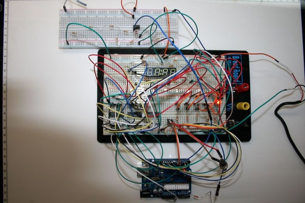
Regardless of whether you are building the circuit exactly as shown in the circuit diagram or maybe using a slightly different transformer, display type or other components, you should breadboard the circuit first in order to ensure it works and that you understand how it works.
In the pictures you can see that breadboarding the whole thing required a couple of boards as well as an Arduino Uno board. So in order to program the microcontroller or experiment or make changes to the software, you will initially need the microcontroller IC on a UNO board so that you can connect a USB cable to it and your computer to upload the program or make software changes.
Once you get the clock working on the breadboard and have your microcontroller programmed, you can unplug it and plug it into the socket on your final build permanent clock on prototype board. Be sure to follow anti-static precautions when you do this. Use an anti-static wrist strap while handling the microprocessor.
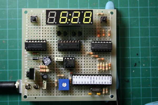
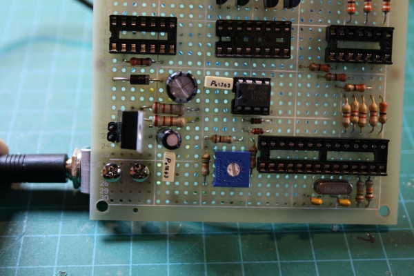
Step 3: Circuit Construction on Protoboard
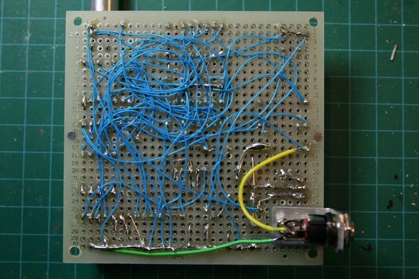
The circuit is constructed on a piece of prototype board and wired point to point using #30 AWG wire wrap wire. It provides a tough and reliable result. Because the transformer I have has a male 5mm plug on the end of the cable, I mounted the corresponding female receptacle on the back of the board by cutting, bending and drilling a piece of 1/2″ wide flat aluminum strip to make a custom bracket and then bolted it to the board with small 4-40 nuts and bolts. You could just cut off the connector and solder the remaining power wires to the board and save yourself about 20 mins work, but I did not want the transformer permanently attached to the board.
Step 4: Creating a Socket for the Display and Giving It Legs
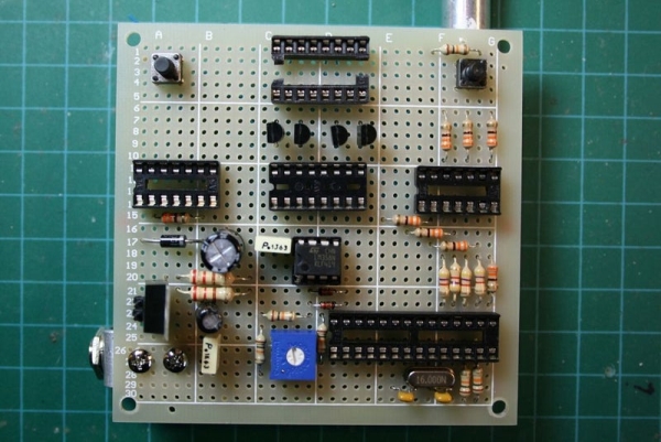
Because the display has 16 pins, 8 one each side, with a pin spacing which is wider than a standard 16 pin IC socket we need to adjust the socket size to fit the display. You can do this by simply using a pair of wire cutters to snip the plastic connecting the two sides of the socket, separate them and solder them separately to the board with a spacing that matches the spacing of the pins on the display. It is advantageous to do this so that you don’t have to solder directly to the display pins and expose the display to excessive heat. You can see the socket I have done this to at the top of the board in the picture above.
In order to get the display to stand up right I bolted two 1″ bolts to the bottom two corner holes of the prototype board as shown in the photos to make a simple stand. This was pretty tippy, so if you do this, you might want to put something heavy on the back of the bolts to stabilize it.
Step 5: Checking the Circuit Board Wiring and Preparing to Calibrate
Once the circuit board is wired up but before plugging in the ICs or display or powering it up, it is a good idea to check the board connections with a DVM. You can set most DVMs so that they beep when there is continuity. Set your DVM in this mode and then following your circuit diagram, check as many of the circuit connections as possible. Check for an open circuit, or close to it, between the +5V and Ground points. Visually check that all components are connected to the correct pins.
Next connect your transformer to the circuit and power it up. Check that you have exactly 5V DC on the 5V power rail with either a scope or DVM before you plug in any ICs or the display.
Next plug in ONLY the Op-Amp U5 IC in preparation for the next step. Here we will check that our cross over circuit is generating a square wave and adjust potentiometer RV1 for a clean 60 Hz signal.
Step 6: Circuit Calibration
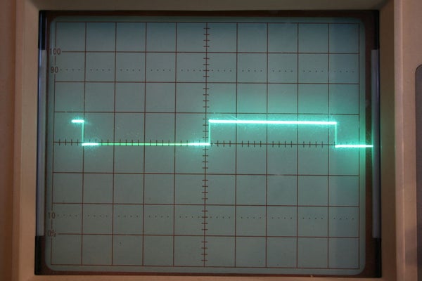
The only calibration to be done is to adjust the potentiometer RV1 for the correct level of signal feeding the cross over detector. There are two ways to do this:
1. Put a scope probe on pin 1 of U5 and make sure to connect the scope probe ground wire to the circuit ground. Next adjust RV1 until you have a clean square wave as shown in the above picture. If you adjust RV1 too far one way or the other you will either have no square wave or a distorted square wave. Ensure that the square wave’s frequency is 60 Hz. If you have a modern scope it will probably tell you the frequency. If you have an ancient scope like I do then ensure the square wave period is approximately 16.66ms or 1/60 secs.
2. Using a frequency counter or DVM in Frequency mode measure the frequency at Pin 1 of U5 and adjust RV1 for exactly 60 Hz.
Once this calibration is done, power off the circuit and plug in all of the ICs and the display to complete the circuit construction.
Step 7: The Arduino Program
The program is fully commented so that you can figure out the details of every step. Due to the complexity of the program it is difficult to describe every step, but at a very high level this is how it works:
The microprocessor receives the incoming 60 Hz square wave and counts 60 cycles and increments the seconds count after every 60 cycles. Once the seconds count reaches 60 seconds, or 3600 cycles, the minutes count is incremented and seconds count is reset to zero. Once the minutes count reaches 60 minutes the hours count is incremented and minutes count is reset to zero. the hours count is reset to 1 after 13 hours, so this is a 12 hours clock. If you want a 24 hour clock just change the program to reset hours to zero after 24 hours.
This is an experimental project, so I tried to use a Do-While loop to suppress switch bounce on the Set and Increment buttons. It works reasonably well. When the Set button is pressed once, the Increment button can be used to step through the hours shown on the display. When the Set button is pressed again, the increment button can be used to step through the minutes shown on the display. When the Set button is pressed for a third time, the time is set and the clock starts running.
Patterns of 0 and 1 that are used to display every number on the 7-segment displays are stored in the array called Seven_Seg. Depending on the current clock time, these patterns are fed to the 74HC595 IC and sent to the display. Which of the 4 digits of the display is turned on at any one time to receive this data is controlled by the microprocessor via the display Dig 1,2,3,4 pins. When the circuit is powered up, the program first runs a test routine called Test_Clock which sends the correct digits to light up every display with a count from 0 to 9. So if you see this when you power up you know you have built everything correctly.
Step 8: Parts List
1 – Transformer 120VAC to 12VAC approx 100ma or more
1 – Prototype board approx 3.5″ x 3.5″
1 – 4 digit 7 segment display YSD-439K2B-35 or equivalent (Sparkfun)
2 – Small PCB mount push buttons N.O (any)
4 – 2N3904 NPN transistors
8 – 330 ohm resistors
2 – 74LS04 Hex inverters
1 – 74HC595 serial to parallel 8 bit shift register
1 – LM358 OP-AMP (Comparator)
1 – ATMEGA328P Microcontroller (Creatron)
4 – 4.7K resistors
7 – 10K resistors
1 – 1N4007 or 1N4001 diode
2 – 1N4148 diodes
1 – 120 ohm, 1/2W or 1W resistor
1 – PCB mount 10K potentiometer
1 – 470uF 25V capacitor
1 – 7805 TO220 package voltage regulator
1 – 10uF 10V capacitor
2 – 0.1 uF 10V capacitors
1 – 16MHz crystal (Sparkfun)
2 – 22pF capacitors
1 – Female power jack (Optional to fit male plug if any on your wall transformer)
2 – 16 pin IC sockets
2 – 14 pin IC sockets
1 – 8 pin IC socket
1 – 28 pin IC socket
2 – 1″ long approx #4 or #6 bolts and matching nuts
2 – 1/4″ long #4-40 bolts and matching nuts
1 – piece of 1/2″ wide flat aluminum strip custom cut and drilled to size
#30 AWG wire wrap wire
#22 AWG wire
Solder
Source: Arduino Digital Clock Synchronized by the 60Hz Power Line