Summary of Arduino Data Glasses for My Multimeter
Summary: A maker built inexpensive Arduino data glasses (head-up display) displaying Bluetooth data on an OLED reflected through a mirror and lens into a transparent acrylic visor. The main challenge was designing optics to form a virtual image the eye can focus; the prototype used a ~100–110 mm focal length lens (Fresnel or magnifier lens), cost about €70, and evolved from cardboard housing to a 3D printed enclosure. Electronics include an Arduino, OLED, Bluetooth, battery and charging resistor modification.
Parts used in the Arduino Data Glasses:
- Arduino (microcontroller)
- OLED display
- Bluetooth module
- Acrylic transparent visor
- Mirror for reflecting the display
- Lens (approximately 100–120 mm focal length, e.g., Fresnel lens or head-mounted magnifier lens)
- Battery (small Li-ion, example 280 mA)
- Charging circuit board (with resistor modification)
- 3k resistor (original) and 5.6k resistor (replacement to reduce charging current)
- Cardboard enclosure (for prototyping)
- 3D printed enclosure (final version)
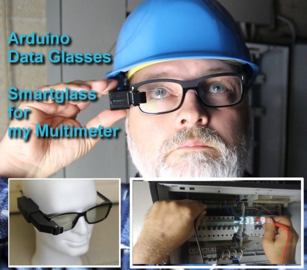
Trying to build a cheap Arduino Data Glasses for everybody. Why? I just wanted one.
It’s working, and now it can even help to avoid accidents. From the first idea to the working prototype, it took 4 Month
The challenge was, that It should be constructed out of common materials that can be found easily. The project is more about how to build the optical system for this HMD. One thing is clear, you can not just place a screen in front of your eyes, because it will not be possible for them to focus it.
In the logs you can see from the first tests to what I have now.
The optical design was the most difficult part, but I think I found a solution for this. The costs of the prototype amounted to +-70Euros.
And now I have a Head-Up Display For Hight Voltage
Step 1: What’s Inside and How Does It Work?
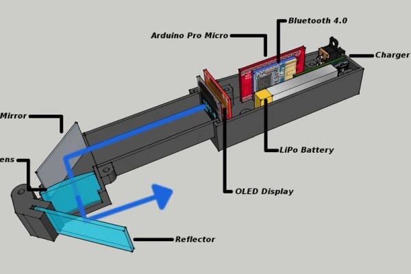
The received Bluetooth data is displayed, on the OLED display. It’s then reflected over the mirror, goes through the lens and you can see the picture in the little transparent acrylic glass.
That is the simple explication. The details are coming now 🙂
Step 2: The Lens. the Most Tricky Part
I made the data glasses work, but it was more a trial an error challenge.
So I took a google crash course in optics.
First of all I had to understand the difference between a real and a virtual image with lenses. Then a very important thing is, that a human eye can only focus an object at a distance of min 25cm. And all what I needed was this formula (1/f) = (1/o) + (1/i) where f is focal length of the lens o is object distance to the lens and i is the distance of the virtual image.
Here are the values I used:
with f=10cm and o=7.3cm
you will get an i=-27.03cm (virtual images have always a negative value) and a magnification M=3.7
Lens Calculation Website
http://hyperphysics.phy-astr.gsu.edu/hbase/geoopt/image4.html
Step 3: Alternative Lens
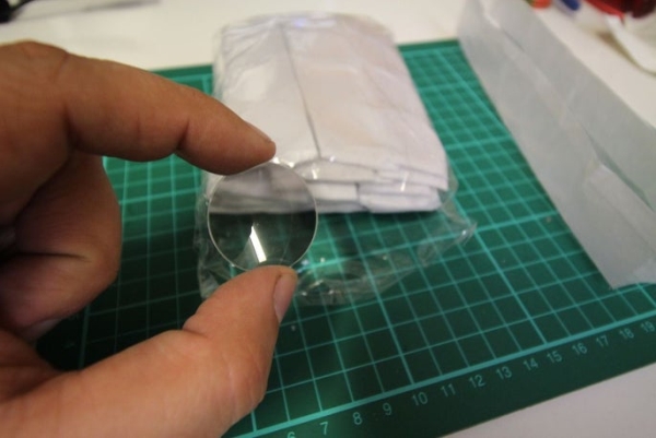
I know that the lens is hard to find. I uses one of a cheap cardboard wich has lenses with a Focal length of 100mm and not like the google cardboard 45mm
UPDATE
I think I found a good solution for the lens. I just checked the physical data (FL = +- 110mm). and they should be perfect. I have no time right now, to test them, but if somebody could do it and give me a feedback, this would be great. A small Fresnel lens should do the job. and they are cheap and easy to find on the internet. And you can cut them with a cutter.
Like this one https://www.amazon.com/Small-Fresnel-Lens-Magnifier-Pack/dp/B00CF5ZXKK
An otherf alternative is a the lens of a head mounted magnifier. Normally they deliver 3 to 5 lenses and one of these should have a FL between 110mm and 120mm which works fine. It’s just a little bit heavier and not so easy to cut
Step 4: Electronics
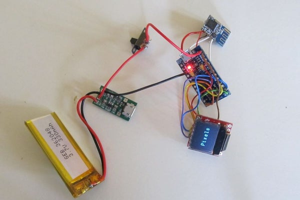
Here are all the electronic parts for the data glasses
I just used a smaller battery in the final version.
To use the 280mA battery, I had to change the 3k resistor against a 5.6k resistor on the original board. The charging current is now reduced to +- 200mA.
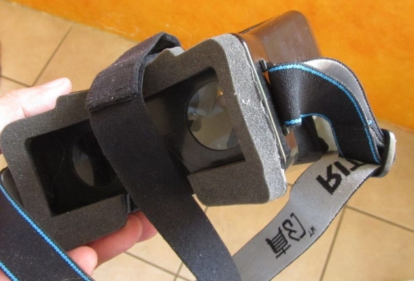
Step 5: the Enclosure
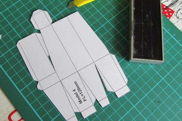
For the first tests, I used an enclosure made out of cardboard. This was a cheap solution and worked very well
For the final version, I used my 3D printer. The style file has been created in 123design. I need to make a few modifications to the design, but it’s not bad for the first try.
Read more: Arduino Data Glasses for My Multimeter
- How does the Arduino Data Glasses display data?
Bluetooth data is sent to the OLED display, reflected by a mirror, passes through a lens, and appears on the transparent acrylic visor as a virtual image. - What lens focal length was used for the optical system?
The project used lenses around 100 mm to 110–120 mm focal length to create a virtual image the eye can focus on. - Can a Fresnel lens be used for this project?
Yes, a small Fresnel lens with a focal length around 110 mm is suggested as a cheap, easy-to-cut option. - Why is the lens design important for the glasses?
The lens is crucial because the eye cannot focus on objects closer than about 25 cm, so the lens must produce a virtual image at a suitable distance using lens formula calculations. - What modification was made to the charging circuit?
The 3k resistor on the charging board was replaced with a 5.6k resistor to reduce the charging current to about 200 mA for a 280 mA battery. - How long did it take to develop the working prototype?
The prototype progressed from idea to working device in about four months. - What materials were used for enclosures during development?
Initial tests used a cardboard enclosure; the final version used a 3D printed enclosure designed in 123design. - What is the approximate cost of the prototype?
The costs for the prototype amounted to approximately 70 Euros.