The objective of this instructable is to guide your way throw the entire making process of building a BuildersBot machine. An open design Arduino Controlled CNC Router that can also perform 3D printing.
The instructions will cover all areas such as design, mechanics, electronics and software.
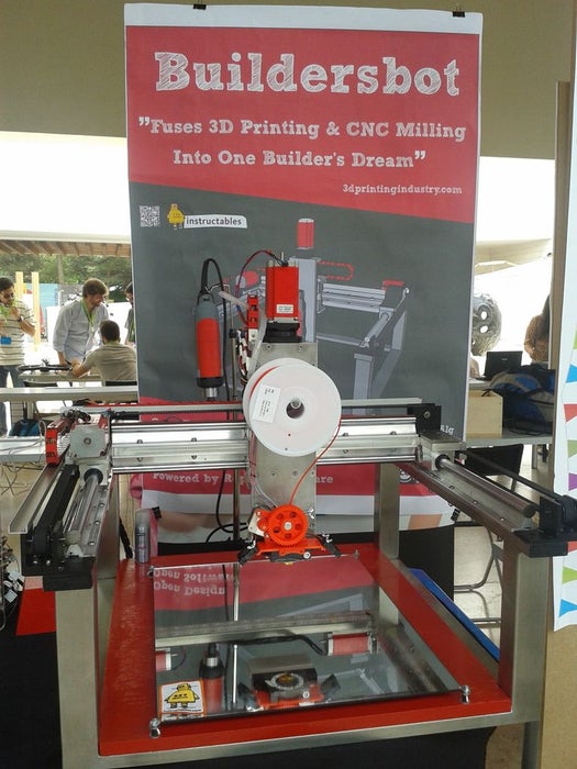
But before you go any further take a look at machine’s concept design:
And also the machine build photos and the machine in action:
Finally check out the insane effects of the RGB led’s on BuildersBot:
Warning Viewer Discretion Advised (Strong Language)
Step 1: The BuildersBot OpenDesign (Sketchup)
To view the the machine in 3D just Download the attached sketch file and access the BuildersBot OpenSource Design (in metric system and is in 1 by 1 scale).
Use this design as much as possible for guidance during this instructable.
NOTE: Use trimble/google sketchup to open the file.
Step 2: List of Materials and Costs
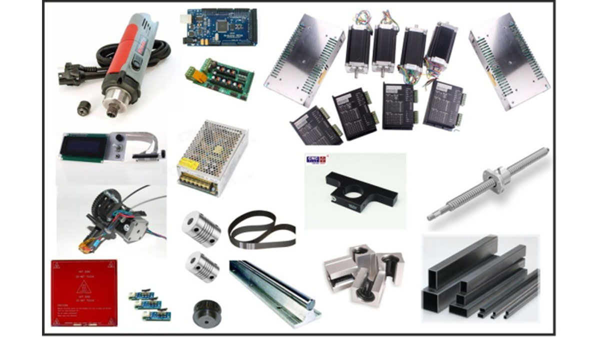
In order to build a BuildersBot you will need the following list of “ingredients”:
8 – SBR20UU CNC Linear Ball Bearing Support – 35€
4 – SBR16UU CNC Linear Ball Bearing Support – 20€
1 – Ballscrew with Fitted Anti Backlash Ballnut RM1605-C7: 350mm – 100€
1 – XD Coupling 25mm X 30mm Bore Size: 8mm to 12mm – 10€
3 – Motor coupling Bore Size: 8mm to 6mm – 15€
2 – SFC16 Precision ground round shaft with support (16 mm) – 30€
2 – SFC20 Precision ground round with shaft support (20 mm) – 70€
2 – SFC20 Precision ground round shaft with support (20 mm) – 60€
3 – Timing Belt 1790-5M-15 – 45€
1 – Shielded Ball Bearing 686-ZZ (Pack of 10) – 20€
6 – Metric Timing Pulley – 35€
1 – 15mm Aluminum plate – 50€
1 – Kress Milling Spindle 1050W – 150€
1 – 43mm Euro Neck Spindle Mount, Bracket Clamp for Kress Milling Spindle – 35€
1 – 4 Nema 23 Stepper Motor 425oz + 4 microstepping Driver + Power Sup – 255€
1 – MIG Welded Stainless steal frame 125€
1 – Stainless Steal marine grade screws, washer, nuts etc – 50€
1 – 10mm Acrylic Case – 50 €
1 – Arduino Mega + Ramps 1.4 Board + LCD- 100€
1 – 12V power supply – 15€
1 – Complete Greg’s extruder J-head hot end + motor + ABS extruder + endtops + hotbed – 100€
1 – Lock tight + lubricant + paint – 35€
1 – Wires, cables, tubs, connectors, plugs – 20€
2 – Low noise fans – 15€
1 – MDF board for the BuilderBot Bed – 15€
1 – 5 Meter RGB LED Stip – 30€
The total approximate cost of these items is around 1485€
Step 3: Understanding the 3 Dimensional Cartesian Coordinate System
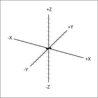
“The 3 dimensional Cartesian coordinate system consists of three number lines, labelled X, Y and Z, set at 90 degree angles to each other. The origin, is where the three axes cross each other.”
3D … duh 🙂
The Buildersot works/moves within a 3 dimensional Cartesian coordinate System, allowing the machine to position its tool (drill bit or hot end) in any location inside the 3 dimensional work space.
The X axis will move the tool from left to right, the Y axis will move the tool from back to forth and finally the Z axis will move the tool up and down inside the work area.
In summary: The 3 dimensional work space is mapped using XYZ coordinates, this means that we can precisely control the position of the tool holder inside the work space.
Step 4: The BuildersBot Stainless Steel Frame
The objective:
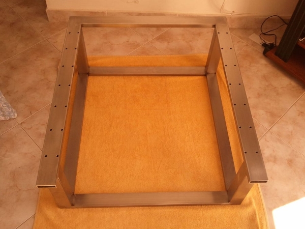
Build a frame made from rectangular and square stainless steel tubes.
Items needed:
The frame is composed by 11 stainless steel parts (for dimensions consult the 3d open design).
4 – rectangular tubes on the bottom of the chassis
4 – square tubs positioned vertically
3 – rectangular tubes on the top frame
Tools needed:
– TIG welder
– Angle grinder and cutting tool
– Drill machine
– Carbide drill bit ( 6.5mm )
Instructions:
1- Using a cutting tool:
– Cut 2 stainless steel rectangular tube with 50x20x750mm that will function as the bottom vertices of the frame
– Cut 2 stainless steel rectangular tube with 50x20x750mm that will function as the bottom vertices of the frame
– Cut 4 stainless steel square tubs with 50X50x250mm that will function as the vertical pillars of the frame
– Cut 1 rectangular stainless steel tube with 60x20x750mm (that will function as the bottom vertices of the frame)
– Cut 2 rectangular stainless steel tube with 60x20x750mm (that will function as the bottom vertices of the frame)
2 – Tap and drill 12 holes with 6.5mm diameter in both upper parallel rails (according to the position of the holes of the calibrated rail supports) (for distances consult the 3d sketch).
3 – Weld the 4 rectangular tubs that make the bottom frame. Be careful to align the tubes perfectly. Next weld the 4 vertical columns, and finally the 3 renaming top tubes that from an open frame.
4 – After welding all the tubes together, use angle grinder to trim the excess weld from the welding points.
5 – Clean the chassis with special acid for stainless steal , and finally polish it with any appropriate material.
Read more: Arduino Controlled CNC / 3D Printer Hybrid