This is a relatively simple clock to build, in terms of the hardware required and in terms of hooking up all the wires. The complexity lies in the software, which I’ve conveniently included as part of this instructable 🙂
This instructable illustrates a few things:
* Keeping relatively accurate time on an Arduino without using a real time clock (RTC)
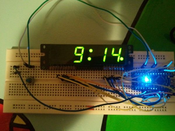
* Using a basic clock display – the type you see on most alarm clocks. In this case an LTC-617.
* Multiplexing a display to make it appear all digits are shown at once, even though the display only display one digit at a time.
* Controlling the brightness of individual digits (more LEDs on = dimmer digit)
I originally built this for a different platform, and decided it was time to port it to Arduino!
I hope you enjoy this instructable and find it useful – it makes a great start for so many evil project possibilities!
Step 1: Parts
For this Instructable, you will need:
1 Arduino (I used an Arduino-nano)
1 LTC-617 clock display (you might need to solder male headers onto it)
many jumper wires
1 button
1 resistor: 10k or close (to prevent short between gnd and 5v on button press)
For me this was a no-cost project as I already had all the parts.
The clock display was part of a grab bag I bought long ago. I imagine they should be very inexpensive and might even be salvageable from old clock radios.
Little buttons and resistors are also salvageable from old electronics (reset buttons from old computers, for example), and also very inexpensive to purchase.
The Arduino starts at around $15 on eBay, though I would expect anyone would be unlikely to ever use it for only just this one project!
I used a breadboard for easy connections, but that’s not necessary.
Step 2: About the LTC-617 Clock Display
I received several of these displays in a grab bag of electronics a few years ago, so I decided to put one to use.
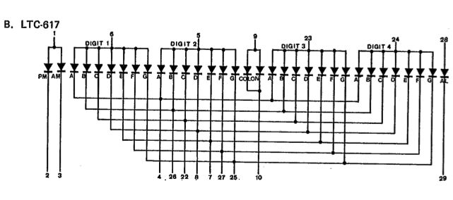
This particular display does not have any smarts added to it. All of the pins go directly to the LEDs in the display. That means the smarts have to come from the software that controls the display.
You’ll notice from the attached picture that each of the 4 digits is controlled by a single IO line, and all digits share the IO lines for the individual 7 segments. Which means that you cannot have two different digits shown at the same time.
To get around that limitation, we use the Arduino to show each digit for just a fraction of a second. When this is done repeatedly and fast enough, our eyes just see one steady display. In the code you can change the timing to make it blink each digit more slowly, if you wish to see how it works.
You could save some I/O pins and software complexity by using a 4511 binary (BCD) to 7-segment decoder, which allows you to use 3 Arduino pins to send a binary number to the decoder chip, which then does all the work of figuring out which LEDs in the digit to light up.
Here is a good link explaining how the decoder chip works: http://www.doctronics.co.uk/4511.htm
That link also contains the logic table that shows which segments need to be on for any given number. I used something similar to this when I was building my software.
So what was the point of all that? My point is just that different displays will behave differently and the code would need to be modified accordingly.
Step 3: Make the connections
There are quite a few wires that need to be hooked up, but if you go carefully and double check each line as you hook it up, it should be pretty straightforward.
I’m assuming you already know the basics of getting your Arduino going, so I won’t get into those details. If not, there are a lot of nice examples online to get you started (I like the ones at oomlout.com).
Here are the connections that need to be made. On the left is the pin of the LTC, on the right is the Arduino pin. For example, LTC pin 4 is connected to Arduino pin digital7. nc means that pin of the LTC is not connected to anything.
1 LTC-617 clock display
many jumper wires
1 button
For more detail: Arduino Clock using Standard Clock Display