Summary of Arduino Circuit to Dim LED with Potentiometer
This lesson combines analog input and output to create an adjustable LED brightness circuit. By reading a potentiometer's position as a voltage divider, the system maps the 0–1023 range to a 0–255 PWM signal. This scales the LED brightness directly according to the knob's rotation, utilizing specific pins and components for current limiting and voltage control.
Parts used in the Adjustable LED Brightness Circuit:
- Arduino
- LED
- Potentiometer
- 330 ohm resistor
- Analog pin 9
In Lesson 8 you learned to write analog voltages on the Arduiono, and in Lesson 10 you learned to read analog voltages from the arduino. In this lesson we will combine what you did in lessons 8, 9, and 10 to create an LED with adjustable brightness. The brightness will be set based on the position of the potentiometer. In order to do this, we need to set the potentiometer up as a voltage divider, and we need to drive the LED from one of the analog pins. For this example, I am using pin 9. The circuit schematic I am using is shown below.
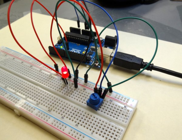
In placing the LED into the circuit, remember that you must always put the longer leg towards the positive voltage. In the case above, the longer leg should be connected to the resistor, and the shorter leg connected to ground. Also remember that we are using a 330 ohm resistor in the circuit to limit the current through the LED.
The goal now is to use what you learned in the last three lessons. You will want to read a value from the potentiometer, and then write a voltage to the LED based on the reading from the potentiometer. Remember that when you read an analog voltage between 0 and 5 volts, the arduino will report a number between 0 and 1023, with 0 representing 0 volts, and 1023 representing 5 volts.
Similarly, when you are writing an analog voltage between 0 and 5 volts, you must write a number between 0 and 255. If you write a “0” value, that corresponds to 0 volts. If you write a value of 255, that will output 5 volts. So, you must scale your write values between 0 and 255 to get voltages between 0 and 5 volts.

The tricky thing now is that we want to dim the LED based on what value we read from the potentiometer. If we read a 0 value from the potentiometer, we want to write a value of 0, which corresponds to a voltage of 0. If we read a value of 1023 from the potentiometer, then we will want to write our maximum voltage of 5 volts, which means we need to write a value of 255. Basically, we need to scale our read values, which will be between 0 and 1023 to suitable write values, which should be between 0 and 255.
For more detail: Arduino Circuit to Dim LED with Potentiometer
- How is the LED brightness controlled?
Brightness is set based on the position of the potentiometer. - Can the potentiometer be used as a voltage divider?
Yes, the potentiometer must be set up as a voltage divider. - Which analog pin is used to drive the LED?
Pin 9 is used to drive the LED in this example. - What value does the Arduino report when reading 0 volts?
The Arduino reports a number between 0 and 1023, where 0 represents 0 volts. - Does writing a value of 255 output 5 volts?
Yes, writing a value of 255 outputs 5 volts. - What happens if you read a value of 1023 from the potentiometer?
You need to write a value of 255 to output the maximum voltage of 5 volts. - Why is a 330 ohm resistor included in the circuit?
The resistor is used to limit the current through the LED. - Which leg of the LED connects to the resistor?
The longer leg should be connected to the resistor.