Summary of Arduino Button Tutorial
This tutorial guides users on implementing robust button handling in Arduino projects using polling within the `loop()` function. It covers wiring a momentary switch with an internal pull-up resistor, managing electrical noise through software deglitching via sampling, and distinguishing between button states and events. The guide emphasizes that while interrupts offer higher accuracy, simple polling is sufficient for most basic to moderately complex applications, provided loop execution times remain consistent.
Parts used in the Arduino Button Project:
- Momentary switch (button)
- Arduino board (AVR/ATmega chip)
- Breadboard
- Internal 20 kOhm pull-up resistor
What’s simpler and dumber than a button, you ask…
I say: behind a button, unexpected things can hide. And within a program that does various things, handling a button can be tricky. The nice thing is that interesting functions can be built with a simple dumb button.
This tutorial will address these aspects:
- wiring and configuring pins, using pull-up/pull-down resistor,
- deglitching,
- detecting states versus events,
- detecting long presses,
- and some object-oriented programming.
The programming approach is based on polling, encouraged by the Arduino loop() principle, and which is perfectly acceptable for simple to moderately complex Arduino projects. We’ll require the duration of each loop() execution to be “fairly” the same each time.
More advanced implementations, not covered here, may include the usage of interrupts and timers. They are more accurate, but also harder to understand.
This tutorial is intended to people with a basic first Arduino experience (i.e. with knowledge of the IDE, and of the compilation, flashing and running of sketches).
In the following ZIP file, the four sketches used in this tutorial can be found.
 arduino–button_tut.zip
Step 1: Connecting the Button
The Button
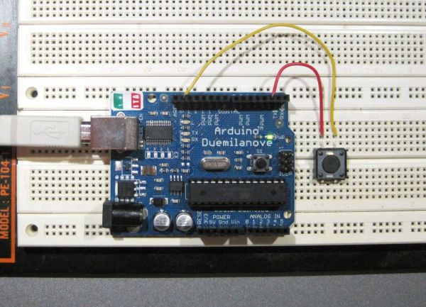
This is a momentary switch, with one stable position (open) when no force is exerted, and conducting (closed) when pressed. It is one of the simplest electro-mechanical sensing device.
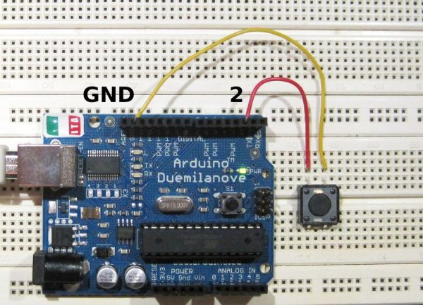
Connect the button like illustrated in the photo of this step.
(Don’t be impressed by the size of my breadboard. A small one will be actually handier.)
The I/O Pin
The AVR (aka ATmega, i.e. the Atmel chip powering the Arduino board) has several I/O pins. I/O means that they can be freely configured by software as input or output.
Pin 2 will be a good choice for our example. It will be used to measure the state of the button: pressed or released.
Pull-up Resistor
The pin has to be connected to somewhere via the button. The question is: where.
A first idea would be to go to VCC. VCC is the usual denomination for the supply voltage, here 5V.
So when the button is pressed, the pin would be connected to VCC, and the software would read HIGH. But when the button is released, the pin is connected to nowhere, aka “floating”, and will be exposed to noise, and the software will read HIGH and LOW in an erratic way.
So the solution is to use a so-called pull-up or pull-down resistor. Such a resistor ensures that the pin is always connected to GND or VCC, directly or via the resistor, depending on the button position.
Fortunately, the AVR chip has, internally, a 20 kOhm pull-up resistor that can be connected to the pin (internally). The pin must be configured as input, and its value, in this situation, tells whether the pull-up is connected (otherwise the value defines, when the pin is configured as output, its output state).
With this pull-up, we’ll connect the pin to GND through the button, and have these situations when the button is released, respectively pressed:
  Button not pressed:

               VCC
                |
           20K | |
      internal | |
       pull-up |_|
                |
                |                 _____
      input ––––*––––––o–––––––––o     o––––– GND
                      pin       released
                                 button
Input is isolated from GND, so only connected to VCC via the resistor. No current flows.
Without the pull-up resistor, the input would be “floating”.
  Button pressed:

               VCC
                |    :
           20K | |   :
      internal | |   :
       pull-up |_|   :  some current flows
                |     `- - - - - - - - - ->
                |
      input ––––*––––––o–––––––––o–––––o––––– GND
                      pin        pushed
                                 button
Input is now directly connected to GND. Some current flows through the resistor.
In both cases, we now have a clearly defined situation.
Consumption
When the button is pressed, the resistor gets a voltage difference equal to VCC, and a current I is flowing:
I = VCC / R
= 5 / 20,000 = 0.25 mA
Corresponding to consuming the power P:
P = VCC2 / R
= 52 / 20,000 = 1.25 mW
This is not much, and is consumed only when the button is pressed. Often, pull-up and pull-down resistors have even greater values, consuming hence less power. If you don’t have particular reasons, use this handy 20k internal pull-up.
Polarity
Had we a pull-down at our disposal, we would have connected the pin to VCC instead of GND, and read HIGH upon press, which is more logical. But since we have a pull-up only, we’ll have to reverse the polarity by software, at pin sampling.
For more about I/O pins, follow http://www.arduino.cc/en/Tutorial/DigitalPins.
Programming
The configuration of the AVR pin (as input and with pull-up enabled) is described in the code below.
Code
––––––––––8<––––––––––
#define BUTTON_PIN 2

void setup()
{
  ...
  pinMode(BUTTON_PIN, INPUT);
  digitalWrite(BUTTON_PIN, HIGH); // connect internal pull-up
  ...
}

void loop()
{
  ...
}
––––––––––>8––––––––––
Step 2: Sampling, Deglitching, and Reading States
Glitches
Buttons are like many things: imperfect. Even when they give a firm mechanical sensation, they generate a couple of oscillations when the button position changes.
These oscillations are called glitches or bounces. They can be eliminated by adding a capacitor (introducing some delay), or by software.
Filtering by Sampling
Often, your Arduino application is loop()-based, i.e. does something, then sleeps awhile, repeatedly. The button state sampling code can look like:
void loop()
{
  // handle button
  boolean button_pressed = read_button();

  // do other things
  do_stuff(button_pressed);

  // sleep a moment before next iteration
  delay(DELAY);
}
This means that at least DELAY milliseconds elapse between successive button samplings. Depending on DELAY, this will make us insensitive to the glitches. The responsiveness is not totally accurate, but largely sufficient: there will be some jitter in the magnitude of DELAY. It must be insured that the things we do during each loop take a “small” and comparable time for each iteration.
The first picture of this step shows the glitches and the periodic sampling (indicated in blue).
Button
For more detail: Arduino Button Tutorial
- How should the button be wired for this project?
Connect the button pin to GND through the button, utilizing the AVR's internal 20 kOhm pull-up resistor connected to VCC. - Can I use external resistors instead of the internal ones?
The article suggests using the handy 20k internal pull-up unless there are particular reasons to do otherwise. - What causes glitches when pressing a button?
Glitches or bounces are caused by imperfect mechanical oscillations that occur when the button position changes. - How can I eliminate button bounces without adding hardware?
You can eliminate glitches by using software filtering through periodic sampling within the loop. - Does the Arduino loop() need to take a constant amount of time?
Yes, it must be insured that the things done during each loop take a fairly small and comparable time for each iteration. - What is the advantage of using interrupts over polling?
Interrupts are more accurate but also harder to understand compared to the polling approach covered here. - How much power is consumed when the button is pressed?
Approximately 1.25 mW is consumed, which corresponds to a current flow of 0.25 mA. - Why must the polarity be reversed in the software?
Since the internal pull-up connects to VCC and the button connects to GND, the logic is inverted compared to a standard pull-down setup.