
Summary of ARDUINO Burglar Alarm Using Infrared Emitter-Detector pair
This tutorial demonstrates building an inexpensive Arduino-based intrusion detection system using an IR emitter-detector pair. When an object blocks the infrared beam, the detector's reading changes, triggering a buzzer alarm. The project involves assembling the circuit on a breadboard and uploading custom code to monitor sensor values via the serial monitor for threshold calibration.
Parts used in the Arduino Intrusion Detection System:
- Arduino Uno R3
- Breadboard
- Connecting wires / Jumper cables
- Infrared Emitter LED (White)
- Infrared Detector LED (Black)
- PCB mount BUZZER
- 1kohm Resistor
- 10kohm Potentiometer
In this tutorial i will show you , how to make a simple Inexpensive Intrusion Detection(Burglar alarm) using an Arduino Uno board . This project uses the Infrared Emitter-Detector pair to detect intrusion and triggers an alarm as soon as the object crosses the infrared field .
** To see a Similar Project Made with an LDR click here
**To see more simple arduino projects check out my blog
http://learnthroughexample.blogspot.in/search/label/arduino
Step 1: REQUIREMENT :
- Arduino uno R3
- Breadboard
- Connecting wires / Jumper cables
- Infrared Emitter and Detector pair LED(not the sensor module)
- PCB mount BUZZER
- 1kohm Resistor
- 10kohm PotentiometeR
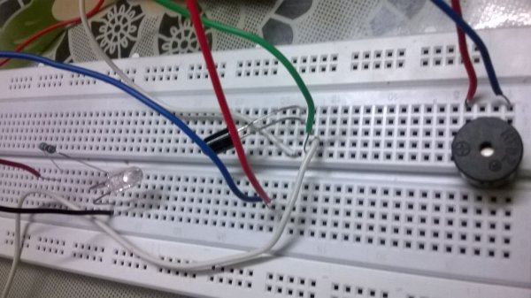
** the white LED is the Infrared emitter ,While the black is the Infrared Detector .
 Step 2: CIRCUIT DIAGRAM :
Step 3: SOURCE CODE:
int dtect=8;
int sense=A0;
int buzzpin=9;
void setup()
{
  pinMode(dtect,OUTPUT);
  pinMode(sense,INPUT);
  pinMode(buzzpin,OUTPUT);
  digitalWrite(dtect,HIGH);
  Serial.begin(9600);
}
void loop()
{
  int val=analogRead(sense);
  Serial.println(val);
  if(val>=1005)
  {
    buzz(50);
  }

}
void buzz(unsigned char time)
  {
    analogWrite(buzzpin,170);
    delay(time);
    analogWrite(buzzpin,0);
    delay(time);
  }
Step 4: DISCUSSIONS :
First build the circuit according to the circuit diagram provided .
Now i will explain to you how the circuit works .
- The white Led you see in the pictures is an Infrared Emitter . You power it on like a normal LED .
- Now if this is your first time with an IR Led , its very common that you’ll mistake your LED to be spoiled as you wont find it glowing ,but that isn’t the case really .
- Infrared light is out of the visible spectrum range so even if it is glowing , you wont be able to see it with naked eyes.
- To see if your emitter LED(White) is working properly : switch on your cell phone camera and see the LED through it , you will see that there is a purple Glow .
- This ensures that your IR emitter (White ) is working perfectly and it is emitting light of a particular range of frequency . Now lets come to the Black LED .
- The back LED is the IR detector. The reason that it is made black is that Black color has the highest absorption ; so it Absorbs most of the infrared light Emitted by the Emitter .
- Now what happens if an object stands in between the Emitter and the detector ?? . OBVIOUSLY the amount of infrared radiations intercepted by the detector will now be lesser due to the obstruction .This is the catch !! .
- When such a situation occurs , I trigger the alarm to denote Intrusion .
 Now that you’ve got your concept right , LETS FOCUS ON THE CODE .
- In line 10 we begin the serial communication to see the values being intercepted on the serial monitor for both the cases i.e
- case 1.) no obstruction in the path of the emitter and the detector .
- case 2.)obstruction in the path of the emitter and the detector .
- for both these cases , we have to observe the values being reflected on the serial monitor , based on which we will decide for which value being exceeded we will be triggering the alarm .
- Note that for my experiment the threshold value was set to 1005 . This might not be the case for you. Hence try to monitor the values that you are intercepting and choose your threshold accordingly .
**Well , hope I have covered all the concepts in detail regarding this project . If you face problems or if you need further detailing on any sub-topic , then please do leave me a comment .
For more detail: ARDUINO Burglar Alarm Using Infrared Emitter-Detector pair
- How can I verify if my IR emitter LED is working?
Switch on your cell phone camera and look at the white LED through it; you should see a purple glow. - Why does the IR detector LED appear black?
The black color has the highest absorption capability, allowing it to absorb most of the infrared light emitted by the emitter. - What happens when an object stands between the emitter and detector?
The amount of infrared radiation intercepted by the detector decreases due to obstruction, which triggers the alarm. - Can I change the threshold value for triggering the alarm?
Yes, the threshold value depends on your specific setup, so you must monitor serial monitor values to choose the correct one. - Does the infrared light from the emitter glow visibly to the naked eye?
No, infrared light is outside the visible spectrum range, so it cannot be seen with naked eyes even if it is glowing. - What pin is used for the IR detector sensor input?
The sensor is connected to analog pin A0, defined as 'sense' in the source code. - Which function is used to control the buzzer sound duration?
The 'buzz' function takes a time parameter to set how long the buzzer sounds before turning off. - What baud rate is used for serial communication in this project?
The serial communication is initialized at 9600 baud rate in the setup function.
