
Summary of Arduino Based Wireless (RF) Weather Station Network
This DIY guide details building a wireless weather station network using Arduino UNO microcontrollers. The system supports up to 254 stations with long-range RF communication via HC12 modules. Users can power sensors with batteries, USB, or solar panels. The project includes custom PCB designs, specific wiring diagrams for Master and Slave units, configuration code, and instructions for 3D printing cases.
Parts used in the Wireless Weather Station Network:
- Custom PCB circuit based on Atmega328p
- Atmega328 microcontroller (with Arduino UNO bootloader)
- 28 pin DIP socket
- 16 MHz crystal oscillator
- Capacitors (2x 22 pF, 1x 100nF ceramic, 1x 10uF electrolytic)
- 10K resistor
- Screw terminal 2P 2.54mm
- Pin Header
- Female 2.54mm connector
- Arduino UNO board (or breadboard alternative)
- Basic 8x2 Character LCD (Black on Green 5V)
- Wireless Serial Transceiver Module HC12
- Trimmer 20kOhm
- DHT-22 or DHT-11 sensor
- DS18B20 Waterproof Temp Sensor
- Photocell / photoresistor
- Push Button Latching
- DC Power Jack
- On/Off Switch
- TTL to USB module
In this DIY guide I will show you how to make your own wireless weather station!
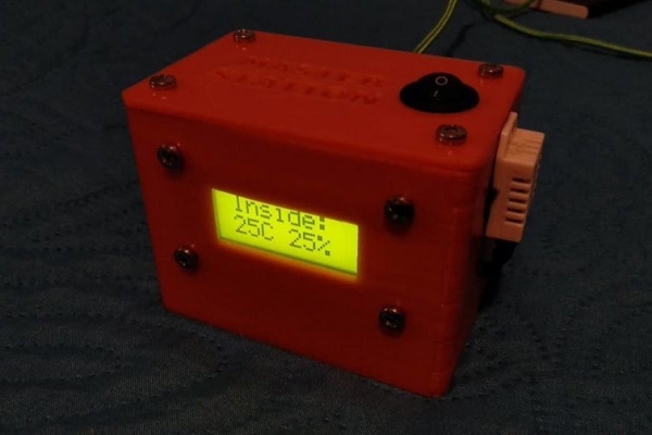
My communication protocol will allow you to have up to 10 sensor stations in your wireless network, but you can change and extend it up to 254 stations! The RF technology and the module that we used will allow you to have a long range distance between your sensors and master station that will have in your room. You can power on your sensor stations with 5V battery (or even with 3.7V) or a solar panel system!
Every “Sensor Station” can have a:
- Photocell / photoresistor Light sensor
- DHT-22/DHT11 Temperature/Humidity Sensor
- DS12B20 Waterproof Temp Sensor
In this project I decided to make my own PCB that is based on Arduino UNO microcontroller – Atmega328p.
Bellow you will find the electronic schematic with PCB layout so you can easily produce it!
Let’s get started!
~Projects can be found here:
https://www.ardumotive.com/arduino-wireless-weathe…
Video presentation:
Step 1: What You Will Need – Hardware Part List
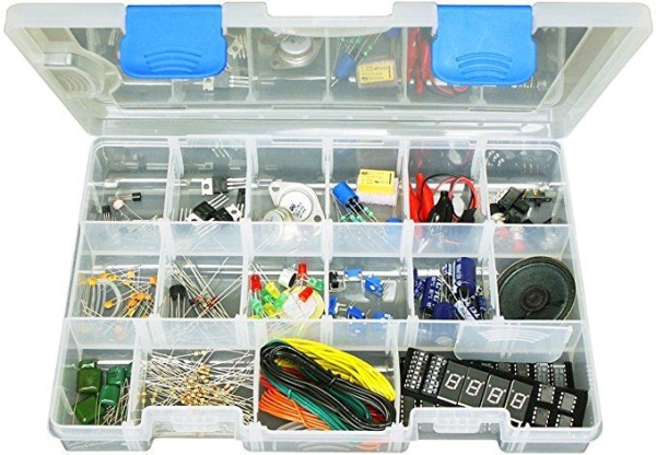
For Master Station you will need:
- Our custom PCB circuit *
- Atmega328 (with Arduino UNO bootloader)
- 28 dip socket
- 16 MHz crystal oscillator
- 2×22 pF capacitors
- 1x100nF ceramic capacitor
- 1x10uF Electrolytic Capacitor
- 1x10K resistor
- Screw terminal 2P 2.54mm
- 2xPin Header
- 1×5 Female 2.54mm
—-> Or use an Arduino board with breadboard
- Basic 8×2 Character LCD – Black on Green 5V
- Wireless Serial Transceiver Module HC12
- Trimmer 20kOhm
- DHT-22 sensor (or any other DHT family sensor)
- Push Button Latching – 12.5mm
- DC Power
- JackOn/Off SW (lcd back light)
~Power by 5V power adapter or USB powerbank~
For every Slave – Sensor Station you will need:
- Our custom PCB circuit *
- Atmega328 (with Arduino UNO bootloader)
- 28 dip socket
- 16 MHz crystal oscillator
- 2×22 pF capacitors
- 1x100nF ceramic capacitor
- 1x10uF Electrolytic Capacitor
- 1x10K resistor
- Screw terminal 2P 2.54mm
- 2xPin Header
- 1×5 Female 2.54mm
—-> Or use an Arduino board with breadboard
One of the following sensors:
- DHT-22 sensor (or any other DHT)
- DS18B20 (Waterproof) and 1×4.7K Resistor
- Photocell and 1x 10K Resistor
~Power by 5V power adapter or USB powerbank or battery pack~
*You will also need a TTL to USB module or an Arduino UNO board for the programming procedure.
Step 2: The Circuit – Electronic and PCB Schematic
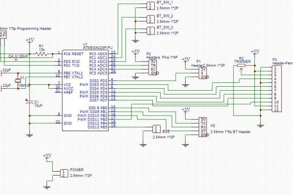
Find the electronic and pcb schematic at link below:
Master Station:
https://easyeda.com/mi.vasilakis/Wireless-Weather-…
Slave/Sensor Station:
https://easyeda.com/mi.vasilakis/slave
You can make any changes you want!
Step 3: Arduino Connection Pins
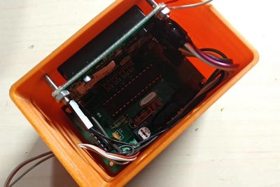
–> For Master Station
LCD
- RS pin to Arduino Pin 3
- EN pin to Arduino Pin 4
- D4 pin to Arduino Pin 5
- D5 pin to Arduino Pin 6
- D6 pin to Arduino Pin 7
- D7 pin to Arduino Pin 11
DHT Sensor
- Data pin to Arduino Pin 2
HC-12
- TX pin to Arduino Pin 8
- RX pin to Arduino Pin 9
–> For Slave/Sensor Station
DHT Sensor
- Data pin to Arduino Pin 8
DS18B20 Sensor
- Data pin to Arduino Pin 2
Photocell
- to Arduino A0
Step 4: The Code
How to program our PCBs:
Connect your circuit with TTL to USB module with 5 cables to the programming header. The pins RX and TX must be cross-connected.
NOTE: If you are using the Arduino UNO board make sure to remove the ATmega328 IC from it first and connect the headers RX to RX and TX to TX pins of the board. The RS pin must be connected to Arduino UNO reset pin.
————-CONFIGURATION—————–
Master
/***CONFIGURATION ****/
const long interval = 5000; // ms
const int slaves = 1; //Number of slaves (max 16) (go to line 95 and complete the if statement for every sensor) /*********************/
Slave
/***CONFIGURATION ****/
const long interval = 5000; // ms
String ADDR = “0”; //Device address from 0 to f #define SENSOR_TYPE 1 // Type of sensor in slave unit. Can be 1 for DHT, 2 for DS18B20 or 3 for PHOTOCELL
/*********************/
Download the code from here and open it with Arduino IDE. Inside you will also find the libraries for this project.
Step 5: 3D Parts
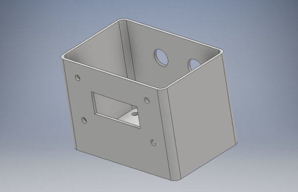
Download and print the case of the master and slave stations with your 3D printer!
Step 6: Well Done!
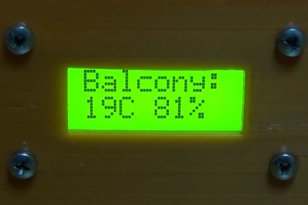
I hope you liked this, let me know in the comments !!!
Source: Arduino Based Wireless (RF) Weather Station Network
- How many sensor stations can the network support?
The protocol allows up to 10 stations by default but can be extended up to 254 stations. - What power options are available for the sensor stations?
You can power the stations with a 5V battery, a 3.7V battery, a 5V power adapter, a USB powerbank, or a solar panel system. - Which temperature and humidity sensors are compatible?
The project supports DHT-22, DHT-11, DS18B20 Waterproof Temp Sensor, and Photocell light sensors. - What is the best way to program the custom PCBs?
Connect the circuit to a TTL to USB module using 5 cables where RX and TX pins are cross-connected. - Can I use an existing Arduino UNO board instead of making a custom PCB?
Yes, you can use an Arduino board with a breadboard, but you must remove the ATmega328 IC if using the board for programming headers. - Does the article mention how to connect the LCD display pins?
For the Master Station, RS connects to Pin 3, EN to Pin 4, D4 to Pin 5, D5 to Pin 6, D6 to Pin 7, and D7 to Pin 11. - Where can I find the electronic schematics for the PCB layout?
The schematics are available via links provided in Step 2 for both the Master Station and the Slave/Sensor Station. - What is the default communication interval set in the code?
The default interval is set to 5000 milliseconds in the configuration section of the code. - How do I identify the sensor type in the slave unit code?
Use the SENSOR_TYPE define where 1 is for DHT, 2 is for DS18B20, and 3 is for PHOTOCELL.
