Summary of Arduino Based Smart Home IOT System
This article guides users in building a budget-friendly smart home system using an Arduino Uno and an Ethernet module. The system allows remote control of up to eight electrical devices via a web interface accessible from any OS-enabled device. It features manual buttons, automatic light control via a photocell, and wireless expansion capabilities through relay or RF modules.
Parts used in the Smart Home System:
- Arduino uno
- Ethernet module (based on W5100 chip)
- Shift Register IC - 74HC595
- 8x buttons
- Resistors (220 Ohm, 1K, 2K, 3K, 10K, 100K)
- Photocell
- Breadboard and breadboard cables
- Screw drivers for outputs and power
- LD1117V33 Voltage regulator (optional)
- 16Mhz crystal osc (optional)
- Ceramic and electrolytic capacitors (optional)
- On/Off switch (optional)
- DC power jack (optional)
- 1A fuse box (optional)
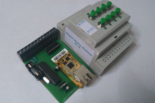
Hello, I am Michalis Vasilakis from Ardumotive.com and in this Instructables guide I will show you how you can easily make your own smart home system based on Arduino uno and an Ethernet module (or shield).
You will be able to use this system from any device (mobile phone, pc, tablet) because the user interface (1st image) is accessible through a browser window. Because of that, it supports all operating systems! You can also control your electrical device from your local area network and (or) from your internet worldwide connection. So, it can be accessible from anywhere! But, this also means that it can be controlled from anyone, so before you make it accessible through your internet connection, consider adding security measures to protect your IOT system.
It supports up to seven +1 outputs for controlling any electrical device in your home. The 8th output can be connected with a photocell to automatically control an outside light (or lamp). These 8 outputs can be expanded to support more output channels. It also has an LED on every output channel and a button to control it manually. Every output channel can be connected with a relay switch or connected to an RF device to control a relay wirelessly. It has a power output (5V up to 1A) for powering up any relay board or other external device.
It can be powered from a 5V up to 1A power adapter, even from your usb 3.0 computer port. If you want to power it up with a different voltage power adapter consider adding a 5V voltage regulator to your circuit.
The hole project cost me less than $40! It’s really easy to make it!!!
Please read and agree with license Attribution – NonCommercial – ShareAlike.
Let’s get started!
Step 1: What You Will Need
For this project you will need:
- Arduino uno
- Ethernet module (or shield) (based on W5100 chip ! important !)*
- Shift Register IC – 74HC595
- 8x buttons
- 8x 220 Ohm, 2x 1K, 2x 2K, 2x 3K, 3x 10K, 1x 100K resistors
- 1x photocell
- Breadboard
- Some breadboard cables
- 8x screw drivers for outputs, 2x for power output and 2x for photocell
(ONLY) If you want to make your own custom – Arduino based – circuit you will also need:
- LD1117V33 Voltage regulator (3.3V output)
- 16Mhz crystal osc
- 2x 22pF ceramic, 1x 0.1uF electrolytic capacitors
- 1x 10K resistor
- On/Off switch
- DC power jack
- 1A fuse box (just in case…)
*The code of this project does not support the ENC28J60 chip!
You can buy them from GearBest.com, good prices and free shipping.
Step 2: Shift Register 595 and Outputs
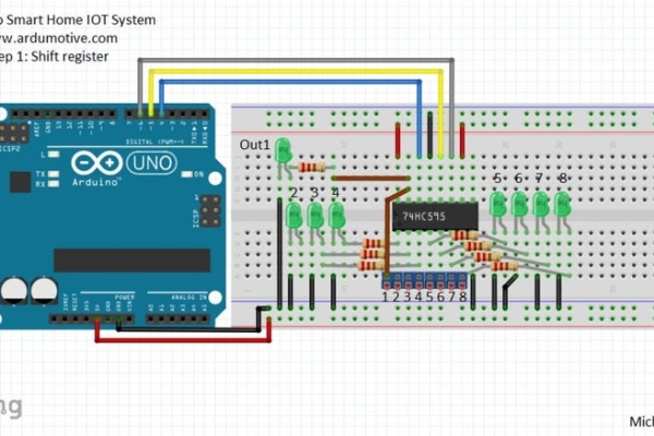
The shift register will give to your Arduino an additional 8 digital outputs, by using only 3 pins on your board!
Here you can find a simple tutorial with the shift register 595 IC and Arduino uno board.
SR 595 and Arduino uno:
- Pin 8 (GND) to GND
- Pin 10 (SRCLR’) to 5V
- Pin 11 (SRCLK) to Arduino pin 6
- Pin 12 (RCLK) to Arduino pin 5
- Pin 13 (OE’) to GND
- Pin 14 (SER) to Arduino pin 4
- Pin 16 (Vcc) to 5V
QA is the first output – QH is the 8th output. We will connect each output with one screw driver – terminal and with an LED through a 220 Ohm resistor.
When you are ready, proceed to the next step.
(tip: You can use the QH’ – pin 9 to add one more shift register ic and expand your outputs.)
Step 3: Buttons and PhotoCell
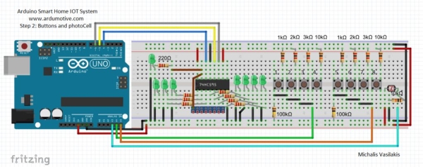
We will add 8 buttons, but we will use only 2 Arduino pins.
Find here a tutorial with multiple buttons through only one analog pin of Arduino board.
- Button BUS line 1 for output 1 to 4 to Arduino analog pin A4
- Button BUS line 2 for output 5 to 8 to Arduino analog pin A5
Add a photocell to control a light bulb. It can be an outdoor light that will automatically turn on at night!
Find here a tutorial with a photocell (or photoresistor).
Use one screw driver – terminal here to expand the sensor for the main circuit.
Photocell will be connected to Arduino analog pin A3.
You can now proceed to the next step.
Step 4: Ethernet Shield
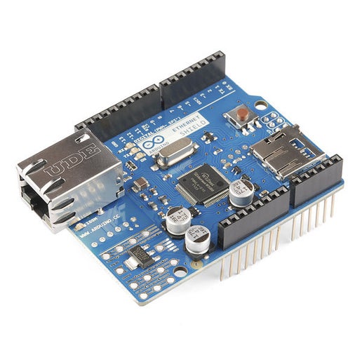
If you have an Ethernet Shield just attached it on the Arduino uno board.
I am using the Wiznet Wiz550io ethernet module. It uses the same library with official Arduino Ethernet Shield (Ethernet.h), the only difference is that it has a unique MAC address.
Some notes about SPI connection:
- MOSI – Arduino pin 11
- MISO – Arduino pin 12
- SCLK – Arduino pin 13
- SCSn – Arduino pin 10
Οptionally for Wiz550io
- RDY – Arduino pin 7
- RST – Arduino pin reset
- INT – Arduino pin 2
Note! Wiz550io must be powered from 3.3V output pin of Arduino uno! Do not use the 5V pin with this module!
Step 5: The Code
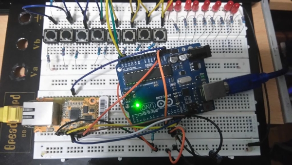
I also made my circuit in an breadboard first to test it.
Here’s the code, embedded using Codebender!
Try downloading the codebender plugin and clicking on the Run on Arduino button to program your Arduino with this sketch. And that’s it, you’ve programmed your Arduino board!
If you want you can make your changes in the sketch below by pressing the “Edit” button. Try for example to change the labels of outputs, for example change “Output1” to “Kitchen Light” (line 164 value=\”Output 1\”).
You can also change the network ip addresses to fit your network configuration.
Photo cell value (line 29) is setted to 300, but you can also change it by pressing the Edit button.
Read more: Arduino Based Smart Home IOT System
- Can this system be accessed from anywhere?
Yes, the user interface is accessible through a browser window from any device with internet connectivity. - Does the project support multiple operating systems?
Yes, because it uses a browser-based interface, it supports all operating systems including mobile phones, PCs, and tablets. - How many output channels can the system control?
The system supports up to seven +1 outputs plus an 8th output connected to a photocell, which can be expanded further. - What chip must the Ethernet module use?
The project requires an Ethernet module based on the W5100 chip; the code does not support the ENC28J60 chip. - Can I power the Ethernet module using the 5V pin?
No, specifically for the Wiz550io module, you must use the 3.3V output pin of the Arduino Uno and not the 5V pin. - How are the buttons connected to the Arduino?
You can connect 8 buttons using only two analog pins by creating two button bus lines for outputs 1-4 and 5-8. - What is the total cost of the project?
The entire project cost less than $40. - Can I change the labels of the outputs in the code?
Yes, you can edit the sketch to change default labels like Output1 to specific names such as Kitchen Light.