
Summary of Arduino Based LED Dimmer using PWM
This article explains how to build a 1 Watt LED dimmer using an Arduino Uno and Pulse Width Modulation (PWM). By rapidly switching the power on and off, the circuit varies the average voltage delivered to the LED, controlling its brightness. The tutorial details the concept of duty cycles and outlines the necessary hardware and software tools required to implement this variable voltage system.
Parts used in the Arduino Based LED Dimmer:
- Arduino Uno
- 5V power supply
- 100uF capacitor
- LED
- Two buttons
- Two 10KΩ resistors
This LED DIMMER is an Arduino Uno based PWM (Pulse Width Modulation) circuit developed to get variable voltage over constant voltage. The method of PWM is explained below. 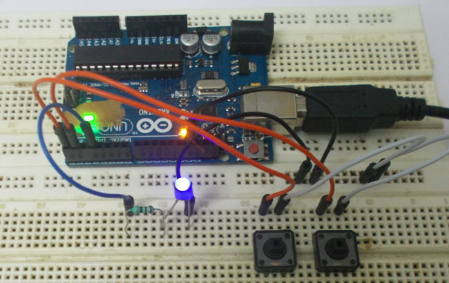 Before we get start building a 1 Watt LED Dimmer circuit, first consider a simple circuit as shown in figure below.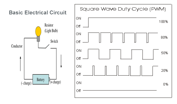
Now if the switch in the figure is closed continuously over a period of time then the bulb will continuously ON during that time. If the switch is closed for 8ms and opened for 2ms over a cycle of 10ms, then the bulb will be ON only in the 8ms time. Now the average terminal over across the over a period of 10ms = Turn ON time/ (Turn ON time + Turn OFF time), this is called duty cycle and is of 80% (8/ (8+2)), so the average output voltage will be 80% of the battery voltage.
In the second case, the switch is closed for 5ms and opened for 5ms over a period of 10ms, so the average terminal voltage at the output will be 50% of the battery voltage. Say if the battery voltage is 5V and the duty cycle is 50% and so the average terminal voltage will be 2.5V.
In the third case the duty cycle is 20% and the average terminal voltage is 20% of the battery voltage.
Now how this technique is used in this LED Dimmer? It is explained in the subsequent section of this tutorial.
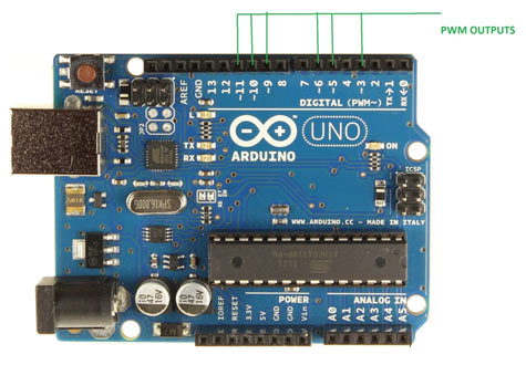
As shown in figure, an Arduino UNO has 6PWM channels, so we can get PWM (variable voltage) at any of these six pins. In this chapter we are going to use PIN3 as PWM output.
Required Components
Hardware: ARDUINO UNO, power supply (5v), 100uF capacitor ,LED, buttons (two pieces), 10KΩ resistor (two pieces).
Software: arduino IDE
Read More: Arduino Based LED Dimmer using PWM
- What is the purpose of the PWM technique in this project?
The method is developed to get variable voltage over constant voltage. - How does the duty cycle affect the output voltage?
The average terminal voltage is determined by the ratio of turn ON time to the total cycle time. - Which pin on the Arduino UNO is used for PWM output?
PIN3 is used as the PWM output in this chapter. - How many PWM channels does the Arduino UNO have?
An Arduino UNO has 6 PWM channels available. - What happens if the switch is closed for 8ms and opened for 2ms?
The duty cycle becomes 80%, resulting in an average output voltage of 80% of the battery voltage. - What software is required for this project?
The arduino IDE is the required software. - Can you vary the brightness using this circuit?
Yes, the circuit allows for variable voltage to control the LED brightness. - What components are listed under Hardware?
The hardware includes an ARDUINO UNO, power supply, capacitor, LED, buttons, and resistors.
