Summary of Arduino Based LED City Model (with Temperature Sensor)
This article details a DIY project to create an interactive cardboard city illuminated by RGB LEDs. The central feature is the ability for the LED color temperature to shift based on the room's ambient temperature, measured by an LM35 sensor. The build involves constructing various structures like an octagonal center building, trees, and other buildings using cardboard, paint, and aluminum foil for light reflection. The system is controlled by an Arduino microcontroller, utilizing the FastLED library to manage the lighting effects dynamically.
Parts used in the Arduino Based LED City Model:
- WS2812b RGB LEDs (neopixels)
- Arduino Uno/nano or similar microcontroller
- Wires
- Cardboard
- Paper
- Acrylic paint
- LM35 temperature sensor
- Plasticine, clay, or stretchy material
- Cotton
- Aluminium foil
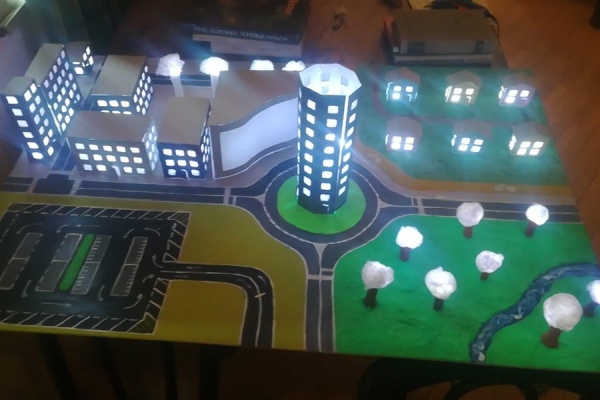
everything is boring without LEDs, so lets make a city out of it!
Basic Idea:
so we build a City mode out of cardboard, then illuminate it with a LOT of RGB LEDs and let the temperature of color change according to room temperature using LM35 Temperature sensor.
Supplies
1. WS2812b RGB LEDs (neopixels).
2. Arduino Uno/nano or any other available arduinos.
3. Some wires.
4. Cardboard.
5. Paper
6. Paint of some kind.
7. LM35 temperature sensor.
8.Plasticine, clay or a stretchy material.
9. Cotton (from pharmacy).
10. Aluminium foil.
Tools:
1. Hot glue gun.
2. Soldering iron (with some soldering wire).
3. Knife or scissors to cut the cardboard and the paper
4. Ruller.
Step 1: Drawing
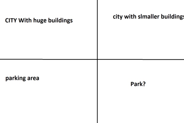
First of all we drew bunch of sketches and listened to Bee Gees – Stayin’ Alive for 8 hours straight to find inspiration. in the end we came up with something…
Step 2: Center Building
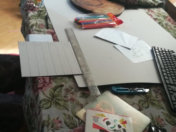
We decided for the main building to be octagonal shape. We cut out the cardboard, then bent it and glued LED strip on it. We painted it and then we filled window holes with Hot glue to give it blurring effect. then placed it in the center of the city.
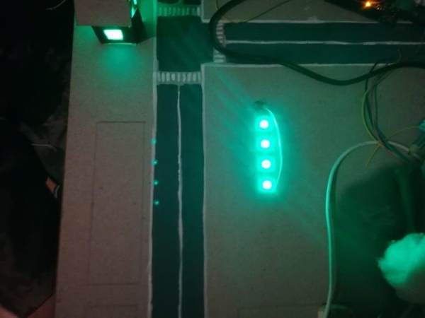
Step 3: Trees
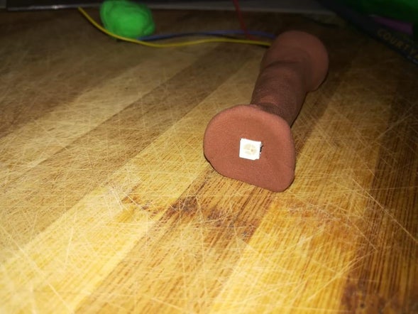
4 Wires should be coming out of the tree roots. its recommended to color code them: Black – GND; Red – 5v; Yellow – Din; Blue – DO;
Step 4: Other Buildings
Then we started to make other buildings. all of them are made the same but with different dimensions. we cut then out, paint them and make windows just like in the previous one. We placed LEDs on the bottom side of the cardboard and made the roof with aluminium foil. aluminium foil helps reflect the light.
Step 5: Park (mostly Just Grass)
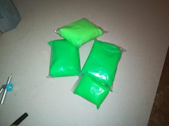
We made some of the grass with this stretchy thingie to give it 3D feeling. Oh and we also drew the river with light blue and white paint. we Use acrylic paint but am sure other types of paints will work too.
Step 6: Wiring
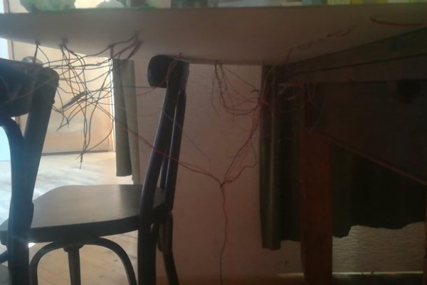
This step should be done only after everything is in place. Connect all GND and 5V wires together and daisy chain LEDs. then connect daisy chain main input to the Arduino digital pin 5. Connect GND and 5v to its pins. External power supply is highly recommended. Just use 5V external powers supply and connect power supply GND to Arduino GND and power supply 5V to Arduino 5V. Wiring can look messy like in my case but its fine…
Step 7: Drawing Parking.
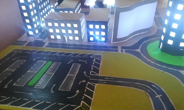
That’s it. We just drew the parking.
Step 8: Arduino Code
#include #define NUM_LEDS 100 #define DATA_PIN 5 #define CLOCK_PIN 8 int val; int tempPin = 3; int BT1 = 0; int BT2 = 1; int BT3 = 2; int BT4 = 3; int BT5 = 4; int BT6 = 5; int BT7 = 6; int BT8 = 7; int WT1 = 28; int WT2 = 29; int WT3 = 30; int WT4 = 31; int TrBl = 0; CRGB leds[NUM_LEDS]; void setup() { FastLED.addLeds(leds, NUM_LEDS); Serial.begin(9600); } void loop() { val = analogRead(tempPin); float mv = ( val/1024.0)*5000; float cel = mv/10; Serial.print(cel); Serial.print(” “); Serial.print(TrBl); Serial.println(); TrBl = map(cel, 25, -10, 0, 255); if (TrBl < 0) { TrBl = 0; } if (TrBl > 255) { (TrBl = 255); } leds[BT1] = CRGB(0, 255, TrBl); leds[BT2] = CRGB(0, 255, TrBl); leds[BT3] = CRGB(0, 255, TrBl); leds[BT4] = CRGB(0, 255, TrBl); leds[BT5] = CRGB(0, 255, TrBl); leds[BT6] = CRGB(0, 255, TrBl); leds[BT7] = CRGB(0, 255, TrBl); leds[BT8] = CRGB(0, 255, TrBl); leds[8] = CRGB(200, 255, TrBl); leds[9] = CRGB(200, 255, TrBl); leds[10] = CRGB(200, 255, TrBl); leds[11] = CRGB(200, 255, TrBl); leds[12] = CRGB(200, 255, TrBl); leds[13] = CRGB(200, 255, TrBl); leds[14] = CRGB(200, 255, TrBl); leds[15] = CRGB(200, 255, TrBl); leds[16] = CRGB(200, 255, TrBl); leds[17] = CRGB(200, 255, TrBl); leds[18] = CRGB(200, 255, TrBl); leds[19] = CRGB(200, 255, TrBl); leds[20] = CRGB(200, 255, TrBl); leds[21] = CRGB(200, 255, TrBl); leds[22] = CRGB(200, 255, TrBl); leds[23] = CRGB(200, 255, TrBl); leds[24] = CRGB(200, 255, TrBl); leds[25] = CRGB(200, 255, TrBl); leds[26] = CRGB(200, 255, TrBl); leds[27] = CRGB(200, 255, TrBl); leds[WT1] = CRGB(0, 255, TrBl); leds[WT2] = CRGB(0, 255, TrBl); leds[WT3] = CRGB(0, 255, TrBl); leds[WT4] = CRGB(0, 255, TrBl); leds[32] = CRGB(200, 255, TrBl); leds[33] = CRGB(200, 255, TrBl); leds[34] = CRGB(200, 255, TrBl); leds[35] = CRGB(200, 255, TrBl); leds[36] = CRGB(200, 255, TrBl); leds[37] = CRGB(200, 255, TrBl); leds[38] = CRGB(200, 255, TrBl); leds[39] = CRGB(200, 255, TrBl); leds[40] = CRGB(200, 255, TrBl); leds[41] = CRGB(200, 255, TrBl); leds[42] = CRGB(200, 255, TrBl); leds[43] = CRGB(200, 255, TrBl); leds[44] = CRGB(200, 255, TrBl); leds[45] = CRGB(200, 255, TrBl); leds[46] = CRGB(200, 255, TrBl); leds[47] = CRGB(200, 255, TrBl); leds[48] = CRGB(200, 255, TrBl); leds[49] = CRGB(200, 255, TrBl); leds[50] = CRGB(200, 255, TrBl); leds[51] = CRGB(200, 255, TrBl); leds[52] = CRGB(200, 255, TrBl); leds[53] = CRGB(200, 255, TrBl); leds[54] = CRGB(200, 255, TrBl); leds[55] = CRGB(200, 255, TrBl); leds[56] = CRGB(200, 255, TrBl); leds[57] = CRGB(200, 255, TrBl); leds[58] = CRGB(200, 255, TrBl); leds[59] = CRGB(200, 255, TrBl); leds[60] = CRGB(200, 255, TrBl); leds[61] = CRGB(200, 255, TrBl); leds[62] = CRGB(200, 255, TrBl); leds[63] = CRGB(200, 255, TrBl); leds[64] = CRGB(200, 255, TrBl); FastLED.show(); delay(50); //this code changes its color temperature according to room temperature. it adds more blue the lower the temperature gets. }
Step 9: Arduino Library
download Arduino FastLED.h library from: https://github.com/FastLED/FastLED
Read more: Arduino Based LED City Model (with Temperature Sensor)
- What is the main purpose of the aluminum foil in this project?
Aluminium foil is placed on the roofs of buildings to help reflect the light from the LEDs. - How does the project change its color temperature?
The color temperature changes according to the room temperature detected by the LM35 sensor, adding more blue as the temperature gets lower. - Which digital pin connects the daisy chain main input to the Arduino?
The daisy chain main input connects to Arduino digital pin 5. - Why is an external power supply recommended for this project?
An external 5V power supply is highly recommended to ensure stable power for the LEDs. - What shape was chosen for the main center building?
The main building was designed with an octagonal shape. - How should the wires coming out of the tree roots be color coded?
Black is for GND, Red is for 5V, Yellow is for Din, and Blue is for DO. - What library is required to run the Arduino code provided?
The project requires the Arduino FastLED.h library. - What material is suggested to give the grass a 3D feeling?
Stretchy material like plasticine or clay is used to create a 3D effect for the grass. - How are the window holes in the center building treated?
Window holes are filled with hot glue to create a blurring effect.