Summary of Arduino-based Graphical Heart Rate Monitor
The author built a portable Arduino-based heart rate monitor using a Polar Wearlink strap and RMCM01 module to record BPM data. The device features an Adafruit TFT touchscreen for real-time graphing and stores logs on a microSD card. While functional, the prototype faced issues with bulkiness, fragility, lack of real-time clock accuracy, and limited user interface options during field testing. Future improvements include adding LiPo batteries, an RTC, better shielding, and enhanced software controls.
Parts used in the Arduino-based Graphical Heart Rate Monitor:
- Polar Wearlink chest strap
- Polar RS300Xsd receiver watch
- Arduino Uno
- RMCM01 OEM module from Sparkfun
- Adafruit 2.8 inch TFT LCD touchscreen shield
- Ni-MH battery
- microSD card
- 32kHz crystal
Introduction:
Like many out there, I enjoy a good exercise session, whether it be indoors or outdoors. As part of that I purchased a Polar branded heart rate monitor, which came with a “Wearlink” chest strap and RS300Xsd receiver watch.
The watch is able to do quite a bit of analysis on its own, in terms of recording heart rate averages, target zones and the like, but without the additional FlowLink device there is no practical way of moving this data to a PC for further manipulation (in any case, the FlowLink device can only synchronise to a website run by Polar).
Having recently started out with the Arduino platform and some simple programming (I can make an LED blink!), a solution seemed obvious, build my own receiver unit and do with the data whatever I please…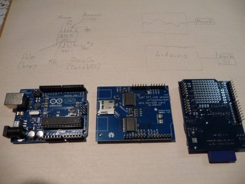
Possibilities and Requirements:
The obvious key requirements of the monitor are:
- To be portable (exercise takes you places, and usually your heart is with you at the time!)
- Must record data to non-volatile storage media for later review.
Ideally it should interface with my existing Polar strap, as I’m not really one for having wires hanging off my chest while exercising.
If possible, I’d also like to add a display of some form to show statistics/heart rate, or some other information, as well as some form of input to change settings on the device without having to reload the sketch.
Putting things together:
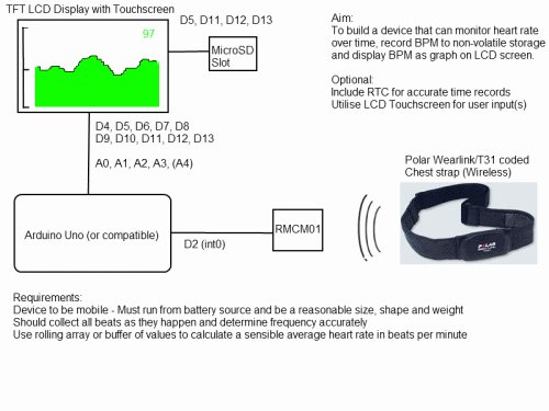
After a bit of research, it turns out an OEM module is available to interface directly with Polar branded heart rate straps, the RMCM01 module available from Sparkfun.
This module does all the hard work of reception and filtering of the signal (on 5.5kHz), and outputs a 1ms pulse at 3 volts for every heartbeat detected. The module is conveniently small and only requires a 32kHz crystal to provide a clock signal. If required, an additional antenna coil can also be added to the module to boost reception range.
As for the brains of the unit, I decided to work with an Arduino Uno due purely to the simplicity of using pre-existing hardware and code from libraries.
I had a spare Adafruit 2.8″ TFT LCD touchscreen from previous experiments, which conveniently covered the storage, display and input options all in one neat package. This wasn’t without a few drawbacks, as this particular shield uses almost all the available pins on the Uno. I also decided to drop the logger shield I originally planned to use for storage and timing, as it would likely misbehave with the LCD (or at least make me write a lot more code than I wanted to) and could be more profitably used elsewhere. As a result I decided to build a new shield for the RMCM01 module, even though this would leave me without the convenience of an RTC for accurate timing.
I also drew myself a rough block diagram of how things might work, as shown below:
Programming:
To ensure I got an accurate BPM reading, I connected the RMCM01 output pin to the Arduino’s D2 to allow me to use one of the external interrupts. Using an interrupt meant that I would never miss a single pulse from the module, and I could avoid introducing any delay() lines, which might disrupt or distort time recordings.
The code fired by the interrupt simply measures time between the current pulse and previous pulse recorded in milliseconds, then uses that to calculate a BPM. To avoid too much random variation, the calculated values are kept in rolling buffer of the last five readings and averaged, as shown in the code segments below:
volatile int diff1 = 0;
volatile int diff2 = 0;
volatile int diff3 = 0;
volatile int diff4 = 0;
volatile int diff5 = 0;
void HRpulse()
{
pulsetime = millis();
rollBuffer();
diff1 = pulsetime – lastpulsetime;
if (diff5 != 0) {
BPM = 60000 / ((diff1 + diff2 + diff3 + diff4 + diff5)/5);
}
lastpulsetime = pulsetime;
}
void rollBuffer()
{
diff5 = diff4;
diff4 = diff3;
diff3 = diff2;
diff2 = diff1;
diff1 = 0;
}
Drawing the graph was a bit more complex, as the TFT LCD module is not really designed as a graphing device. After trying with a line graph, bar chart and scatter plot, I chose the bar chart, as it gave the most visible display of heart rate without drawing crazy averages or being difficult to see due to overlaps. For starters the device draws a single column per pixel width, and has no actual axes (I’m planning to add these in a bit later!).
For convenience of use I also added a simple text display of beats per minute in the top right corner. Each time a column is drawn, the same value displayed is recorded as a line in a CSV file on the microSD card.
To take a peek at the full sketch (this is prone to being updated), please click Here
Trial, field testing and ongoing modifications:
After building and doing some basic tests on the monitor, I decided to take it for a spin on an actual exercise session. Pretty quickly some obvious flaws became apparent:
- The device with a Ni-MH battery is just too bulky, it can’t be readily strapped to the body, wrist or leg (I ended up working with it strapped on my hip)
- Fragility – Shields stuck together work just fine in a lab, but can be pretty easily knocked or jarred while exercising. I ended up half dislodging the upper shields half way through the session and had to rebuild and restart it.
- Not having an RTC is really, really annoying! There is no easy way to figure out what day I did what exercise (particularly if the device is restarted during a session), and the internal clock is prone to a bit of drift which can slightly throw out measurements.
- Further work needs to be done on the BPM calculations, to remove unusual readings caused by poor reception or interference. (This might also be fixable by adding an external antenna loop)
- User interface modifications would really help usability, such as adding definable options via the touchscreen, a Y axis measure and/or grid, and a few more statistics display elements
My next step is to work out a more practical power supply, most likely a set of suitable of LiPo cells, which would be smaller, flatter and lighter. In any case I already have a good balance charger available!
Additionally, I will need to sort out a way to make the whole set of shields more durable to external shocks and stresses. At this stage a simple enclosure box might work, although a custom enclosure would be more useful for adding straps.
I left spare space on the RMCM01 shield deliberately in case I decided to add an RTC of some form further down the line. Most likely I’ll look at adding a suitable 1wire RTC to an available pin when I get around to it, and rework the sketch to support it. At the same time I’ll probably also add an antenna loop and variable resistor for the RMCM01 module to improve and tweak reception.
The user interface really does still need a lot of work, all it does is draw a rough graph based on BPM as sampled per second. As user input is currently non-existant, this can’t be changed without uploading the sketch with new values defined (inconvenient!) In the future I’m planning to store these values on the SD card, as that will make them readily accessible both through the device and on a PC while copying recorded files.
Suggestions and modifications are welcome! As changes are made I will update this page with my progress…
For more detail: Arduino-based Graphical Heart Rate Monitor
- How does the device calculate beats per minute?
The code measures time between pulses using external interrupts and averages the last five readings in a rolling buffer. - Can I view the heart rate data on a PC without the FlowLink device?
Yes, the custom unit records data to a microSD card as CSV files for later review on a computer. - What module interfaces directly with Polar branded heart rate straps?
The RMCM01 module available from Sparkfun is used to receive and filter the signal from Polar straps. - Why was the logger shield removed from the original design?
The logger shield was dropped because it would likely misbehave with the LCD and required too much additional coding. - What are the main flaws identified during field testing?
Flaws included the bulky Ni-MH battery, fragility of stacked shields, lack of an RTC causing timing drift, and poor reception interference. - Does the current version allow changing settings via the screen?
No, user input is currently non-existent and settings cannot be changed without uploading a new sketch. - What power source is planned for future iterations?
The author plans to use LiPo cells which are smaller, flatter, and lighter than the current Ni-MH battery. - How is the heart rate data visually displayed?
A bar chart is drawn on the TFT LCD where each column represents one pixel width of data sampled per second.