If you have kids, you are likely facing the same issues as we did with the Lego sets you bought for them. They assemble and play with them but after a while the sets transform into a single pile of bricks. The kids grow up and you don’t know what to do with this pile.
We decided to recycle the unwanted Lego bricks and created an arcade game.
This step by step guide is a result of several months of work to make the game repeatable and very low cost. Pretty much anyone could repeat this project! The code has been written in such a way that it doesn’t have dependencies and will compile on any Arduino board. And of course the games have been intensively tested by our kids 🙂
How is this game different from many others that have been published before?
First of all, there are 5 games built into it:
- Memory Game (“Simon-Says”-like, similar to Touch Me game)
- Reaction game (similar to Whack-a-Mole game)
- Contest/Competition game (for 2-4 players)
- Melody Game (Push and Play free mode for toddlers and smaller ones)
- War game (for 2-4 adults)
Secondly, it has a great design (from our perspective) and can be easily repeated.
And thirdly, it is earth-friendly because it allows you to recycle the plastic.
At the end of this guide there is also a step-by-step video in case you prefer the video format.
Step 1: Parts List
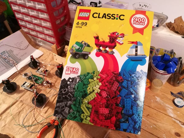
If you like this project but don’t have a pile of unwanted Lego bricks, the easiest would be to buy Lego Classic 10704 set with 900 pieces inside.
Here is list of items you will need to create this project:
- 1kg (2lb) of Unwanted Lego bricks (or similar bricks from another brand such as Mega Bloks)
- 25 x 25 cm base plate for Lego (or similar from another brand). Lego base has 32 x 32 dots. If you don’t have it – the base costs around 3$ incl. postage if you buy online (search term “32 25 blocks“)
- 30 x 30 cm transparent plexiglass piece (5 or 6mm thick)
- 4 x Big Arcade-style 60mm push buttons (I recommend Red, Green, Blue, Yellow) (search term for online stores: “60mm arcade button”). They are the most expensive component of this build at around 2$ each.
- 2 x Momentary push button 16mm radius (I recommend White and Black) (search term: “16mm push button”)
- Power On/Off rocker switch 27x21mm mounting size (I recommend transparent red with 4 pins) (search term: “rocker switch 16a”)
- Arduino Nano
- 1602 LCD display and I2C connection module
- 2 x 4ohm 5W speakers, size 30 x 70 mm (you can use any other small ones but the CAD drawing is done for 30x70mm)
- 8 x 6 cm prototype board or a 830 pin breadboard
- 2×18650 rechargeable batteries (can be recycled from the dead laptop battery)
- Double 18650 battery holder (search term: “holder 2 x 18650”)
- TP4056 charge controller and discharge protector
- 5V step-up converter (smallest 500mA will do)
- Small stuff: some wires, Mini-USB cable or diy plug, Micro-USB socket on PCB breakout, M3 bolts/nuts/washers, 4 x top cover screws
- Resistors:
- 6 x 100 ohm
- 1 x 1k
- 3 x 10k
Step 2: Building the Box
This is the easiest part of the project that you can delegate to your kids.
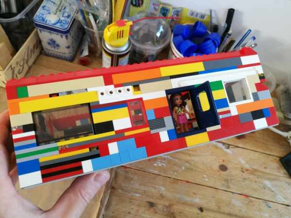
Take the Lego 32×32 point baseplate and lay the walls using the recycled parts. You should have around 9 layers in total. We chose light grey color for the base so that the random-color brick walls are the main focus.
No box will be similar. Be creative when you build the layers. Recycle even small parts – they look cool. Also irregular shapes look nice too. Add windows, windscreens from cars, doors and boxes.
The box must have at least one full-size Lego door. This is needed to install the rocker switch in the wall.
Step 3: Making the Top Cover
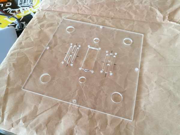
The top cover is made from 5 or 6 mm plexiglas (transparent acrylic sheet). Download the CAD drawing, put it on USB stick and just go to the nearest CNC shop – they will mill it for you. CAD drawing also includes the rocker switch mounting plate (see pic).
You will need to do some finishing of the top plate. Do the edge beveling with the sand paper and a wooden block. Also drill the holes to mount the speakers and the 1602 display. The 1602 display also requires a small triangle milled on the side of the LCD window in the acrylic sheet (see photo). I did this at half-depth using the rotary tool (dremel) and a small router bit.
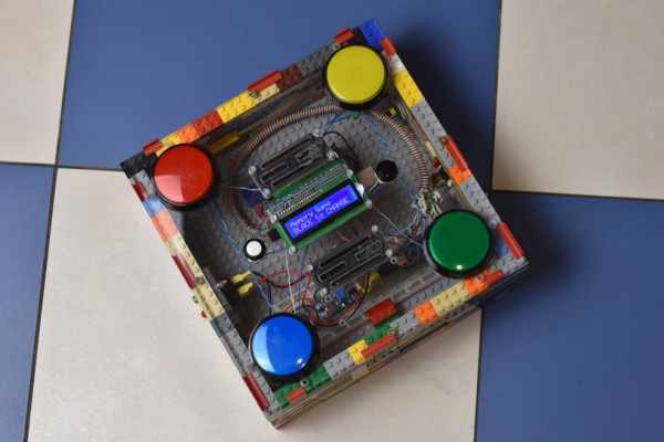
Step 4: Add All Components to the Top Cover
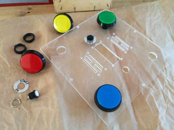
Install the big 4 arcade buttons, 2 game change/select buttons, 2 speakers and a 1602 LCD+I2C module.
Everything is fixed with M3 screws + M3 washers and nuts at the back.
Before you install the arcade buttons – remove the LED light holders. You will need to mod them a little – see next step.
Step 5: Modding the LEDs in the Arcade Buttons
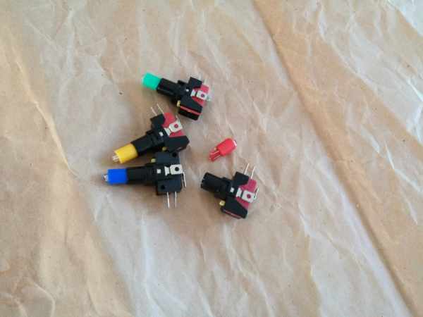
These arcade buttons are designed to operate at 12V. They will work with 5V which is the default voltage for this project but they will be too dim. So I removed the LED sockets from arcade buttons, slid out the LED holders and removed the LEDs with resistors. The 460ohm resistors need to be desoldered and replaced with 100ohm. Once done, I assembled everything back and installed the LEDs with holders into the buttons.
Step 6: (optional) Control Button Labels
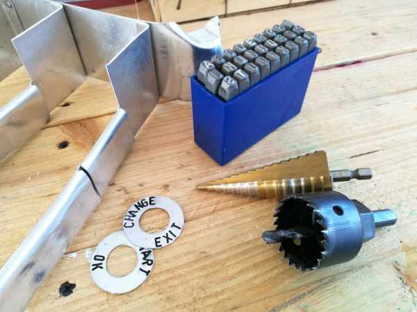
You might have noticed the labels on the 2 control buttons. Our first version of the build did not have them but I decided to add them when I repeated the build second time.
Both buttons have multiple functions depending on the state of the game. White button starts the selected game or confirms the selection during some of the games. Black button changes the selected game or exits during the game.
To create round labels you need a thin aluminium sheet (max 1mm thick), a hole-saw drill bit, stepped drill bit and letter punches (see pic). First you cut the circle using hole-saw. Then you enlarge the inner diameter with the stepped bit and then you use letter punches to create labels. To make letters more visible, use a permanent black marker (sharpie).
Step 7: Making the Breakout Board
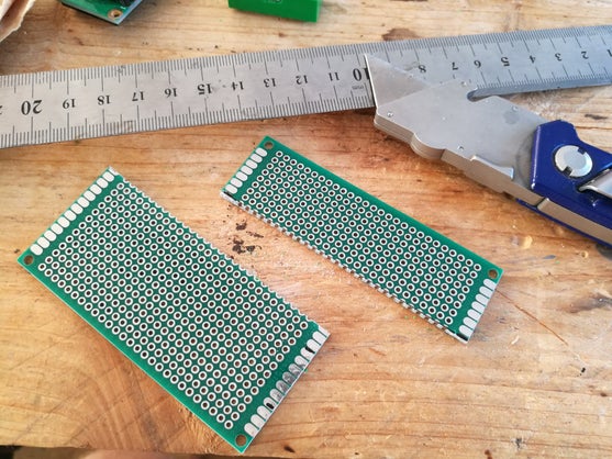
You have two options here. Either to use the breadboard and wire Arduino with cables though the breadboard or to install a small breakout at the back of the LCD panel.
For the first build we used the breadboard (see pic). For the second build we decided to spend more time to create breakout board. The functionality does not change, but there are less wires and the breakout is hidden underneath the LCD panel.
If you opt to go with the breakout board, take the 8×6 prototype board and cut it like shown on the picture. Bigger part will be used for the breakout and smaller for creating power supply.
Solder Arduino Nano onto this proto board.
Source: Arduino Arcade Lego Games Box