This pandemic time has been rough for us all, as it confined us in our homes thus not enabling the opportunity to go outside and meet with family and friends to engage in fun activities of all sorts, such as going to your nearby arcade to play some fun classic arcade games. However, what if I told you that I can bring that same arcade level fun into the safe environment of your own home! This instructable will show you how you can build your very own version of the classic and widely popular ‘Catch the Light!’ arcade game using beginner to intermediate level Arduino components.
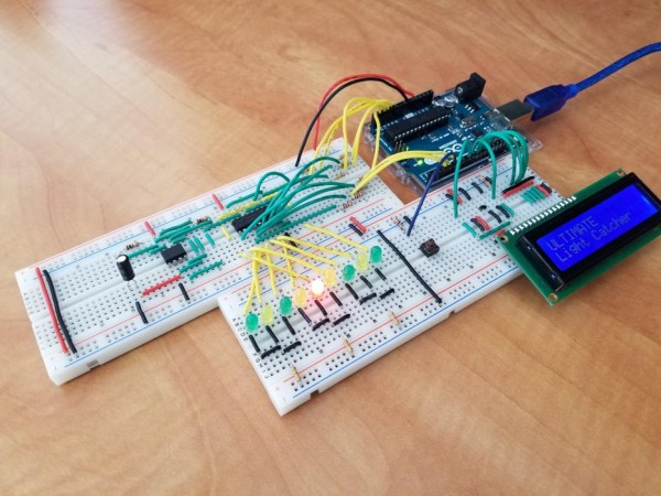
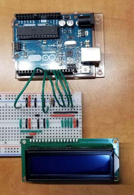
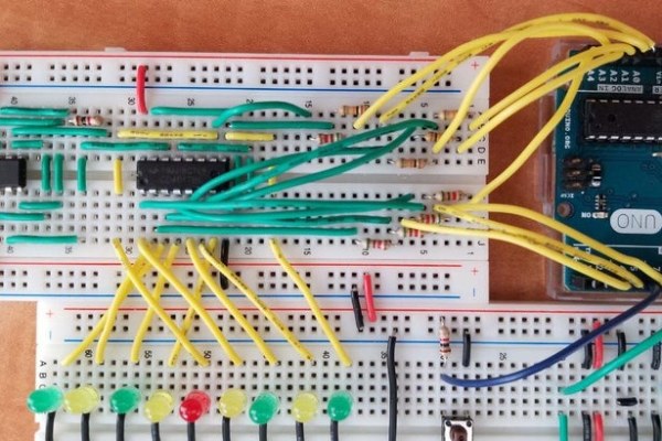
This game functions like how any other light catcher game, there are a total of 9 multicolored LEDs on a breadboard, 4 of them yellow, 4 of them of green, with one single red one in the middle. The LEDs will flash on and then off quickly in a type of pulsing action as they go from left-right. Then located to the right of the group of LEDs there is a push button wired up to the Arduino Uno. Now the objective of the game is to press the button when the red LED flashes on. Whether you were able to catch the LED or not, is information that will be displayed to the user by the Liquid Crystal Display (LCD), which is also wired to the Arduino. The LCD will notify the user about exactly which colored LED they were able to catch and what level of the game they are currently playing, as there are a total of 3 levels in the entire game. With each catch of the red LED the player would progress up one level until they are able to successfully beat level 3, thus wining the entire game. However, they will only receive one chance on each level, if they press the button but fail to catch the red LED, the game will reset and they will be sent back to level 1.
This project can be completely assembled on a real breadboard using physical components, while also having the ability to be completely created electronically on TinkerCAD, a free-to-use online modelling program that allows you to create circuits electronically. In fact, I myself have created the project using both creation methods to show how it can be successfully constructed both physically and electronically. Personally, I recommend physically creating this project as in my opinion, it is a lot more rewarding in the sense that you can physically play your game, while also just being super fun to actually construct.
Step 1: Gathering Materials
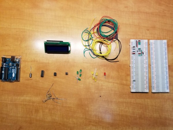
Now if you are deciding to build this project physically then you will need to actually purchase the components listed below unless you already have access to them. Otherwise, if you are constructing this project electronically on TinkerCAD, then you will just need to use the following components on TinkerCAD without needing to purchase them as TinkerCAD already equips its users with all of them.
Supplies:
- Arduino Uno (x1) – Purchase Here
- Solderless Breadboard (x2) – Purchase Here
- Red LED (x1) – Purchase Here
- Green LED (x4) – Purchase Here
- Yellow LED (x4) – Purchase Here
- Jumper Wire Assortment (x1) – Purchase Here
- 16×2 Liquid Crustal Display (x1) – Purchase Here
- Push Button (x1) – Purchase Here
- 100 μF Polarized Capacitor (x1) – Purchase Here
- 555 Timer Chipset (x1) – Purchase Here
- 4017 Decade Counter Chipset (x1) – Purchase Here
- 1kΩ Resistor (x4) – Purchase Here
- 10kΩ Resistor (x4) – Purchase Here
- 5.1kΩ Resistor (x5) – Purchase Here
- 330Ω Resistor (x5) – Purchase Here
Total Cost:
$103.50 + Tax + Shipping
Note: This price may change depending on your country
Step 2: Getting Familiar With the Circuit
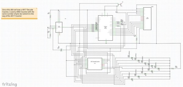
This circuit fundamentally is a combination of two completely separate types of circuits that are united to work together through the Arduino Uno microcontroller. The pulsing and blinking action of the LEDs is completely independent of the Arduino as it is controlled by a completely analog circuit incorporating a 555 timer, and 4017 Decade Counter chipset. Everything else on the other hand such as the liquid crystal display responsible for notifying the critical information to the user, and the pushbutton are completely controlled through the code by the digital output/input pins on the Arduino. However, by attaching jumper wires to the 4017 Decade Counter chip located in the analog circuit, to the analog input pins and digital pins on the Arduino, I am able to successfully keep track of the LED which is currently blinking and then through the code am able to decode that information to tell the program as to which colored LED was caught when the button was pressed so the game can continue accordingly.
The circuit schematic included above should give one a good idea regarding the wiring of all the components within this project, while also providing insight into the inner workings of the circuit. Provided is also the Fritzing file of the schematic if you would like to open it up in the native software and take a closer look at it. However, if needed, you can also visit the my TinkerCAD page on this project to get a better and more real world look at the wiring and using it there by actually activating it and playing the fully functioning game.
Step 3: Background Information/Tips
Before I can actually get started on explaining the wiring and the actual inner workings of the circuits, I would just like to highlight some key points:
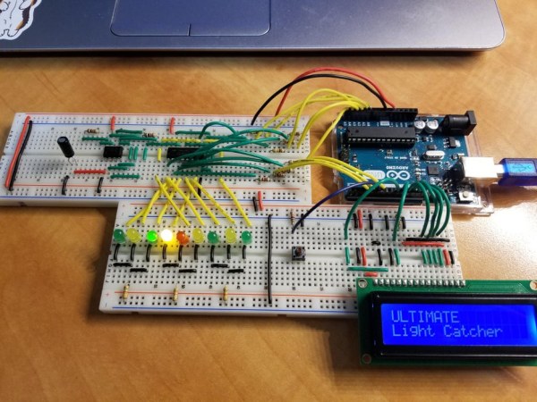
- To actually show the wiring, for each component I will be providing two pictures, one with the wiring done on a real breadboard using physical components, while the other one will be showcasing the wiring electronically on TinkerCAD. The wiring in both do not differ, I am just providing two diagrams to help give a better view of how the wiring should look.
- I strongly recommend color coating your wires throughout this project, with a general pattern being red jumper wires for power, while black colored jumper wires for ground. This will just help differentiate the two, while also helping to overall make it easier for the user to trace back problems and keep everything much more organized.
- Also when I will be referring to ‘rails’ I mean the two long lines of connecting holes on the breadboard located on each side of it. When holding the breadboard vertically, each column of the of the two rails would be marked with either a ‘+’ sign or ‘-‘ sign at the top and/or bottom. These markings help to set each rail for its own purpose, the rail marked with a + is for power while the rail marked with a – is for ground. You would want to attach a jumper wire from each of these rails into the pin marked with 5V and GND respectively on the Arduino. You can attach the jumper wires anywhere in their respective columns as by plugging into one of the holes in the column will activate all the other holes in the that rail with either ground or power. This will help set those rails up on the side making it easy to draw connections with them throughout the breadboard.
- I will not always be mentioning what size resistor I am using when wiring each component and I realize that may get confusing for some people. So to resolve this issue, when looking at my provided pictures you can use this webpage: Resistor Calculator, to exactly find out the size of the resistor I am using in the picture by simply recreating that color pattern in the calculator.
Step 4: Wiring the LCD
Now the Liquid Crystal Display (LCD), is one of the most important components within this circuit as it is responsible for conveying all the vital game related information to the user while the game is running. The LCD informs the user on what LED they caught, as since there is no other indicator, the LCD is the medium for letting the player know if they caught the red colored LED (objective of the game), a green colored LED, or a yellow colored LED. Without this the player won’t even know if they are catching the correct LED or not. Furthermore, the LCD also displays the levels to the user, informing them about the current level they are playing which in turn informs them about their progress to beating the game. As I am sure you have understood by now, the LCD is fundamentally the communication medium between the game and player.
The wiring for the LCD panel follows as shown above and in the circuit schematic. You can also control the brightness of the display using the ‘contrast’ pin of the LCD (3 from the left). If you were to switch that ground wire with a potentiometer which has wires going to the ground and power rails, you can adjust exactly how bright you would like the LCD to be by twisting the knob on the potentiometer. For this project however, that was an unnecessary feature. Therefore I just fixed the brightness by plugging the contrast pin straight into ground using a black colored wire. If you would like to control the brightness of the LCD using the potentiometer, you can do so by following the circuit schematic shown in this insightful LCD Learners Page.
Step 5: Wiring the Push Button
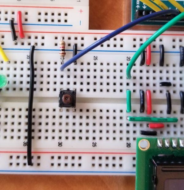
Throughout the entire circuit, the wiring for the push button is the most straight forward and simple. The wiring for it can be seen in the pictures provided above and the circuit schematic, where you have a 1 kilo-Ohm resistor going from one leg of the button into the power rail, with a opposite leg going into ground using a black jumper wire. Then you would just attach a jumper wire going from the power rail which has the resistor to a digital pin ranging from D2 – D13 on the Arduino.
Now the button is really the only input device for the user. The user is to press the button when the red led flashes on in order to progress forward in the game. Linking the press of button with accordance with which LED is flashing is then later calculated using the code.
Step 6: Wiring the LEDs
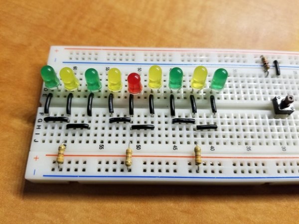
The LEDs are really what the entire game revolves around, as the objective of the game is to press the push button when the red colored LED is flashing on to ‘catch’ the LED. The wiring for the LEDs is also rather simple as currently we are just going to be setting up the LEDs so we can wire the actual current connection to them later on. Since really only one of the LEDs will be flashing at a time and they all use the same size resistor, we could wire all the LEDs with one ground connection going through one 330 Ohm resistor. As you can see in the pictures above I was able to cut down the wiring and overall number of resistors I need to use to a maximum of 3 by having one resistor cover the ground connection for a total of 3 LEDs. However in theory you could cut yours down to only one. Just while wiring make sure to attach the cathode pin of the LED, which is the shorter leg to ground, as attaching the anode will result in the LED to not turn on.
Step 7: Wiring the 555 Timer Chip
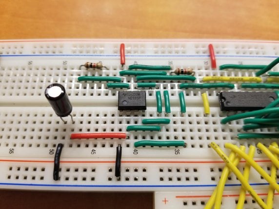
Now we begin construction of the analog circuit which controls the blinking and pulsing effect of the LEDs. The 555 timer chipset is the first step to creating this analog circuit. The 555 timer chipset is responsible for actually creating the pulsing electric current signal that flashes the LED on and then off. The 4017 decade counter which we will work with later is actually responsible for distributing the electric pulse current it receives from the 555 timer to each of the many LEDs to create that pulsing blinking action seen as they flash in order going from left to right, while the 555 timer chip actually creates that pulsing current to turn the LED on and then off. So the way the timer works is that power is fed through the chip and it outputs a HIGH current which is then fed to the 4017 decade counter that would then send that current to its appropriate output, being the LEDs in the set order going from left-right to blink them on. However, as the 555 timer is sending an HIGH electric current output to the 4017 decade counter, it is also feeding the same current to the 100μF capacitor, thus charging it up. The HIGH electric current output from the timer is maintained as long as the capacitor isn’t fully charged up, however once the capacitor fully charges up, it releases that current to the timer which would then force the timer to output a LOW current, which once the LED receives turns it off. Then that LOW electric current is maintained as long as that capacitor is discharging, once fully empty it will begin to charge up again thus allowing for the 555 timer to send out a HIGH electric current instead of a LOW, therefore turning the LED back on. By this pulsing action of a HIGH and then a LOW current, it forces the LED to constantly switch between being off and then back on, thus creating the actual blinking action seen on the LEDs. Then the time that it takes for the capacitor to charge up and then discharge creates this type of analog timer between the pulses of the HIGH and LOW electric currents, thus setting the time for how long the LED stays on, giving the user the chance to press the button to catch the light.
The overall wiring of the 555 timer can be seen in the pictures above and the circuit schematic, you can just follow that to wire your own timer. Just as a side note, changing the capacitor size will effect the duration of how long your LED light stays on for, thereby greatly impacting the overall speed of the pulsing action and in turn the difficulty of the game. You can experiment with the size of the capacitor, making it greater or smaller to make your game easier or harder.
Step 8: Wiring 4017 Decade Counter Chip
Fundamentally, the objective of the 4017 decade counter chip is to distribute the HIGH level electric current it receives from the 555 timer in chronological order to the LEDs going from left to right to create that iconic pulsing effect. The 4017 chip has a total of 10 output pins, each labeled in ascending order. Through the input pin located on the decade counter, we are able to feed the chip the HIGH level electric current pulse from the 555 timer. The chip would then take that pulse and send it to the first output pin, thus letting the current pass through to the first LED in the line of LEDs thus turning it on. Then, when the 555 timer sends the LOW level electric current pulse, the decade counter chip would then send that LOW level current as well to the first LED, thereby turning it off. However, once it turns the first LED off, the chip essentially switches output pins, then when the next pulse of a HIGH electric current arrives, the chip would then send that HIGH level current to the second pin, thus turning on the second LED in the line of LEDs. Then once the LOW level electric current comes from the 555 timer once more, the decade counter would send that LOW level electric current to the second LED thus turning it, after which, it would switch output pins so that the next HIGH level current is passed through to the third output pin to turn the third LED on. By constantly rotating the pins that receive the HIGH level electric current during the time when a LOW level electric in ascending order, the LEDs are flashed on and then off in the pulsing action we require.
Since the LEDs are powered by this analog circuit and not digitally by the Arduino, it is much more difficult to monitor and keep track of the LED currently being turned on. Without keeping track of the LED currently being lit up, we can not find out if the player was able to catch the red LED when the button is pressed. Therefore, to monitor which LED is currently getting power and is flashing on, we have attached jumper wires into the output pins of the 4017 decade counter, that feed the same HIGH electric current being sent to the LEDs to turn them on to the analog input pins and the digital pins set for input on the Arduino. This way by monitoring which output pin is currently sending a HIGH level electric current pulse to the LED thus turning it on, we can know which LED is flashing at all times and could know which LED was flashing when the button was pressed, thereby the game is able to determine if the red LED was caught or not by the player.
The wiring for the decade counter can be found above in the pictures and in the circuit schematic. You can follow that to successfully wire the 4017 decade counter for your circuit.
Step 9: The Code
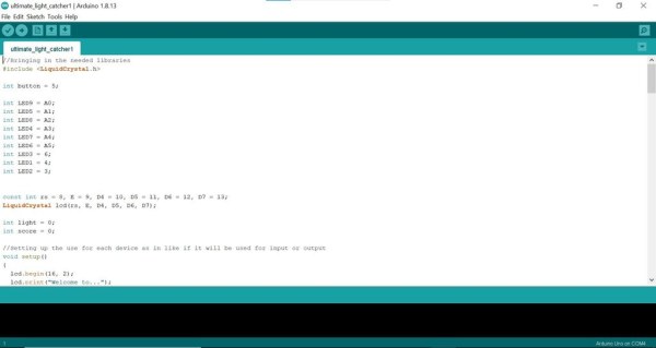
The code is the brains behind the entire project, it controls what is displayed on the LCD while also reading to see if the button is pressed and then according to the LED currently flashing when the button is pressed, would move the game forward. Essentially what would happen in the code is that the code would constantly be monitoring which LED is flashing by reading the HIGH level electric current pulses being sent to the analog and digital input pins on the Arduino from the output pins of the 4017 decade counter. Since each output pin is designated for a different LED on the 4017 decade counter, the jumper wires connecting the Arduino to the 4017 decade counter to pick-up those output signals are set to the appropriate LED number for which the HIGH level electric current output was meant for. Then, as the LEDs begin to flash, according to the LED flashing, the appropriate input pin monitoring the output from the decade counter to the LED would begin to report in that it is getting power. Then according to the input pin reporting in that it is receiving a HIGH level electric current signal, the code would change the value of a integer variable called ‘light’, setting it to a specific value which would help the code later on decode to find out which colored LED was flashing on. Then if the button ever reports in a LOW signal through its input pin to the Arduino, meaning that it has been pressed, the code would see what the variable ‘light’ was equal to when the button was pressed and so accordingly can find out which colored LED was caught by the player. An example would be, if the A0 analog input pin on the Arduino, which is monitoring the output for the 9th LED (a green LED), is reporting in that it is getting power, then the code will change the value of the variable ‘light’ to be equal to 2. This tells the code that currently a green LED is flashing, so when the button is pressed and the code checks to see what the ‘light; variable is equal to, it would find that it is equal to 2, therefore the code will tell the LCD to display that a green LED was caught, and then the code could let the user know that they are back on level from wherever they had progressed up to as they have not caught the red LED. But, say if the A1 pin which tracks the output for the red LED was currently reporting that it was getting power, then the code would change the variable ‘light’ value to equal 1, thus signifying that the red LED is currently flashing. Then if the code picks up that the button is pressed, it would check to see if the ‘light’ variable is equal to 1. Then if it finds that it is equal 1, then it would display on the LCD that the red LED was caught, and so would add a value of one to the ‘score’ variable that holds the score of the user and would send the user to the next level. Then once the ‘score’ variable is equal to 3, it would tell the code that the user has caught the LED three times a row, meaning they have beat the final level of the game, and thereby the LCD would display that the the game is over and the user has won.
I have also included comments throughout my entire code file, this should help you better understand the inner workings of the code and modify it accordingly.
Source: Arduino Activated Light Catcher Arcade Game