The idea of this project is to use an arduino to count every drop of water that goes through the water company meter. Said arduino needs to be connected to my LAN so that I can query it on a regular basis, it also needs to be aware of (real) time so it can timestamp the water consumption.
For this project you will need:
– an arduino
– an ethernet shield + sd card (based on the W5100 chip)
– a proto shield
– a realtime clock (http://www.ebay.com/sch/i.html?_nkw=DS1307+Based+Real+Time+Clock)
– a shmitt trigger (e.g. 74C14N)
– a capacity (1 microF)
– some resitors (20kohm and about 100Kohm)
– a reed switch
– a reed switch-enabled water meter (Gioanola, about 75 euros http://www.gioanola.it/download/downen/08_eloutput_EN_HI.pdf)
Optional:
– a set of passive POE cables (http://www.ebay.com/sch/i.html?_nkw=Passive+Power+over+Ethernet)
references:
http://www.ganssle.com/debouncing-pt2.htm
http://www.ladyada.net/learn/arduino/ethfiles.html
http://www.cosm.com/
http://www.gioanola.it/download/downen/08_eloutput_EN_HI.pdf
I asked a professional to mount a basic water meter right behind the Water Company one (which by law, I cannot touch). Said basic meter has a little magnet on one of its internal wheels and is shipped with a reed switch. So, in practice, everytime a liter goes through it, the switch is closed momentarily. Of course this switch needs to be de-bounced. This could be done by sotfware but we’ll come back to that…
The arduino will serve basic http requests so that it can be queried over the LAN and will also log its activity onto a SD card. So this arduino will be a very busy one… at times. Hence the necessity for the reed switch signals to be conveyed through interrupts so that we never miss a signal. This basically rules out debouncing the switch through software as interrupts and timer do not cohabitate nicely.
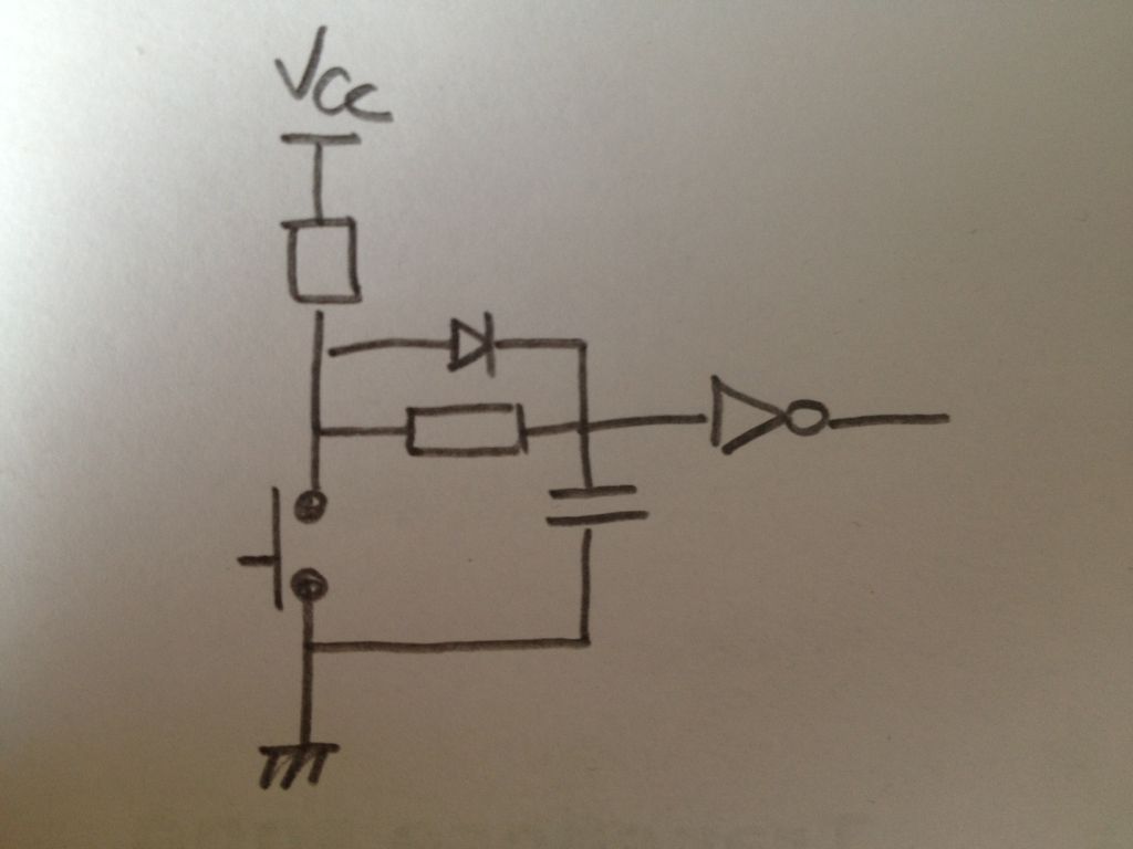
Step 1: RC debouncer

Extensive documentation can be found on the net on this topic (and I found this one particularly useful: http://www.ganssle.com/debouncing-pt2.htm).
In a nutshell, R x C = the time during which you want to smooth out your signal. In my case, I chose 20ms which translates into 1 microF for the capacity and 20kohm for the R2 (well all I had available was 2x 10k), R1 needs to be ‘bigger’ than R2, 100k is good (33k+68k in my case).
A Schmitt trigger later and I have a clean square signal ready to trigger an arduino interrupt.
I tested the setup on a bread board (as you should !) before commiting it to a proper shield.
Step 2: Ethernet and SD card
Using an SD card and an ethernet connection together has proven challenging (both use an SPI connection) until I used the W5100 chip based ethernet shield with an integrated SD card.
Great tutorial there: http://www.ladyada.net/learn/arduino/ethfiles.html
So that’s out of the way.
Step 3: Real time clock, interrupts.
My real time clocks is based on the DS1307 chip, extremely common. Add a coin cell and a (magic frequency) quartz. I liked the form factor of this RTC as it can be plugged directly onto the arduino pins, like a shield.
Interrupts
And interrupts just, well.., interrupt your program so that you can do something based on that event. Try to be quick (like increment a counter and return) so that if another interrupt shows up, you don’t miss it.
Associate a callback method and a pin in your code. Every time a (raising) signals shows up on said pin, you get a callback…
Step 4: Putting it all together
I added a couple of LEDs to my project and a (nice?) box. Given the location of my water meter, POE cables proved handy.
Step 5: Scripting / Code
I started from the ladyada code (ethernet+sd card), added an interrupt. The ip address of the shield is the only thing to be configured and you can do it via a config file on the SD card. So this script can be installed as-is, no line needs modification.
RTC setup : I set the time of my RTC using the d1307_setTime script. Good enough for my purpose. Do it once and for all, that’s the whole point of the RTC module and its coin battery.
Ip address: if config.txt exists on the SD card, its content will override the ip address.
Linux script:
I wrote a script which runs on a linux box and which crontab fires a few times a day. Pretty brute force as it downloads the whole content of the SD card and then ‘explores’ it. It sends me an email with a reassuring ‘everything is OK’ or an alarming ‘too much water consumed today’ !
IP=”192.168.999.999″
EMAIL=”[email protected]”
> crontab -l
00 8,16,23 * * * /bin/bash $HOME/bin/watermeter.sh > $HOME/watermeter.log 2>&1
 water_meter.pde.txt10 KB