
Summary of Analog Speedometer Using Arduino and IR Sensor
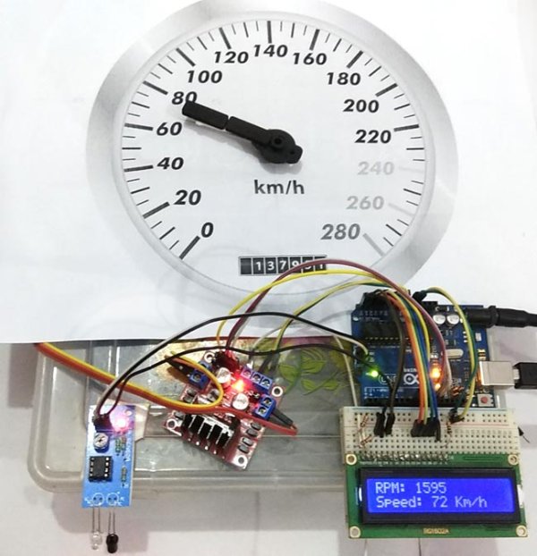
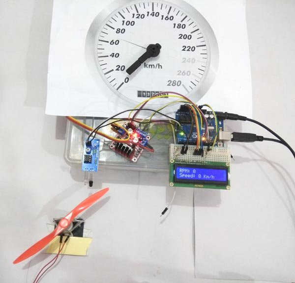
Summary: This project builds an Arduino-based analog and digital speedometer using an IR sensor to detect blade rotations, computing RPM via interrupts and timers, converting RPM to speed (km/h), and driving a bipolar stepper motor to move an analog meter needle while displaying numeric values on a 16x2 LCD.
Parts used in the Analog Speedometer Using Arduino and IR Sensor:
- Arduino
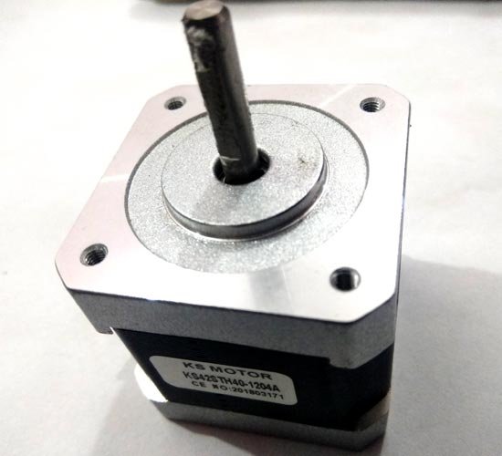
- Bipolar stepper motor (4 wire, 1.8° per step, 200 steps/rev)
- Stepper motor driver (L298N / L293N module)
- IR sensor module
- 16x2 LCD display
- 2.2k resistor
- Connecting wires
- Breadboard
- Power supply
- Speedometer picture printout

Measuring the speed/rpm of a Vehicle or a motor has always been a fascinating project to try. In this project, we are going to build a Analog Speedometer using the Arduino. We will use IR Sensor module to measure the speed. There are other ways/sensors for this, like hall sensor to measure speed, but using an IR sensor is easy because IR sensor module is very common device and we can get it easily from the market and also it can be used on any type of motor/Vehicle.
In this project, we are going to show speed in both analog and digital form. By doing this project, we will also enhance our skills in learning Arduino and Stepper motor since this project involves use of Interrupts and Timers. At, the end of this project you will be able to calculate the speed and distances covered by any rotating object and display them on a 16×2 LCD screen in digital format and also on analog meter. So let’s start with this Speedometer and Odometer Circuit with Arduino
Materials Required
- Arduino
- A bipolar stepper motor (4 wire)
- Stepper motor driver (L298n Module)
- IR sensor module
- 16*2 LCD display
- 2.2k resistor
- Connecting wires
- Breadboard.
- Power supply
- Speedometer picture printout
Calculating Speed and Showing it on Analog Speedometer
An IR Sensor is a device which can detect the presence of an object in front of it. We have used two blade rotor (fan) and placed the IR sensor near it in such a way that every time the blades rotate the IR sensor detects it. We then use the help of timers and Interrupts in Arduino to calculate the time taken for one complete rotation of the motor.
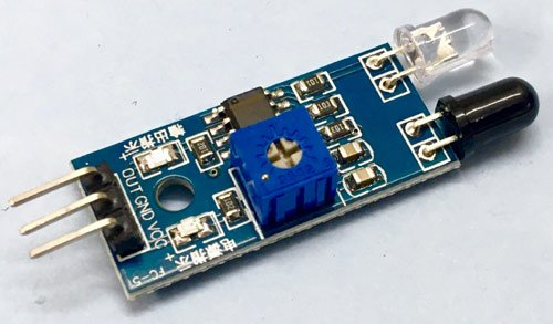
IR Sensor
Here in this project, we have used highest priority interrupt to detect rpm and we have configured it in rising mode. So that whenever sensor output goes LOW to High, function RPMCount() will be executed. And as we have used two blade rotor, It means the function will be called 4 times in one revolution.
Once the time taken is known we can calculate the RPM by using the below formulae, Where 1000/time taken will give us the RPS (revolution per second) and further multiplying it with 60 will give you the RPM (revolution per minute)
rpm = (60/2)*(1000/(millis() – time))*REV/bladesInFan;
After getting RPM, speed can be calculated by given formula:
Speed = rpm * (2 * Pi * radius) / 1000
We know that Pi = 3.14 and radius is 4.7 inch
But first we need to convert radius into meters from inches:
radius = ((radius * 2.54)/100.0) meters
Speed= rpm * 60.0 * (2.0 * 3.14 * radius)/ 1000.0) in kilometers per hour
Here we have multiplied rpm by 60 to convert rpm to rph (revolution per hour) and divided by 1000 to convert meters/hour to Kilometers/hour.
After having speed in kmh we can show these values directly over the LCD in digital form but to show speed in the analog form we need to do one more calculation to find out no. of steps, stepper motor should move to show speed on analog meter.
Here we have used a 4 wire bipolar stepper motor for analog meter, which is having 1.8 degree means 200 steps per revolution.
Now we have to show 280 Kmh on speedometer. So to show 280 Kmh stepper motor needs to move 280 degree
So we have maxSpeed = 280
And maxSteps will be
maxSteps = 280/1.8 = 155 steps
Now we have a function in our Arduino code namely map function which is used here to map speed into steps.
Steps = map(speed,0,maxSpeed,0,maxSteps);
So now we have
steps=map(speed,0,280,0,155);
After calculating steps we can directly apply these steps in stepper motor function to move stepper motor. We also need to take care of current steps or angle of the stepper motor by using given calculations
currSteps=Steps
steps= currSteps-preSteps
preSteps=currSteps
here currSteps is current steps that is coming from last calculation and preSteps is last performed steps.
Circuit Diagram and Connections
Circuit diagram for this Analog Speedometer is simple, here we have used 16×2 LCD to show speed in digital form and stepper motor to rotate the analog speedometer needle.
16×2 LCD is connected at following analog pins of Arduino.
RS – A5
RW – GND
EN – A4
D4 – A3
D5 – A2
D6 – A1
D7 – A0
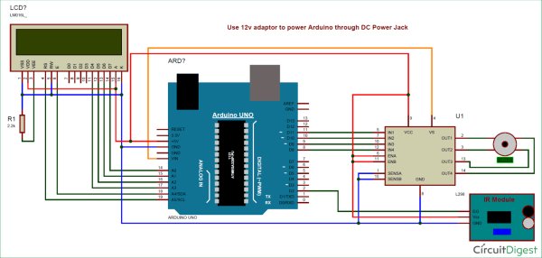
A 2.2k resistor is used to set the brightness of LCD. An IR sensor module, which is used to detect fan’s blade to calculate the rpm, is connected to interrupt 0 means D2 pin of Arduino.
Here we have used a stepper motor driver namely L293N module. IN1, IN2, IN3 and IN4 pin of stepper motor driver is directly connected to D8, D9, D10, and D11 of Arduino. Rest of connections are given in Circuit Diagram.
Programming Explanation
Complete code for Arduino Speedometer is given at the end, here we are explaining few important part of it.
In programming part, we have included all the required libraries like stepper motor library, LiquidCrystal LCD library and declared pins for them.
#include<LiquidCrystal.h>
LiquidCrystal lcd(A5,A4,A3,A2,A1,A0);
#include <Stepper.h>
const int stepsPerRevolution = 200; // change this to fit the number of steps per revolution
Stepper myStepper(stepsPerRevolution, 8, 9, 10, 11);
After this, we have taken some variables and macros for performing the calculations. Calculations are already explained in the previous section.
volatile byte REV;
unsigned long int rpm,RPM;
unsigned long st=0;
unsigned long time;
int ledPin = 13;
int led = 0,RPMlen , prevRPM;
int flag = 0;
int flag1=1;
#define bladesInFan 2
float radius=4.7; // inch
int preSteps=0;
float stepAngle= 360.0/(float)stepsPerRevolution;
float minSpeed=0;
float maxSpeed=280.0;
float minSteps=0;
float maxSteps=maxSpeed/stepAngle;
After this, we initialize the LCD, Serial, interrupt and Stepper motor in the setup function
void setup()
{
myStepper.setSpeed(60);
Serial.begin(9600);
pinMode(ledPin, OUTPUT);
lcd.begin(16,2);
lcd.print(“Speedometer”);
delay(2000);
attachInterrupt(0, RPMCount, RISING);
}
After this, we read rpm in loop function and perform a calculation to get speed and convert that into steps to run stepper motor to show speed in analog form.
void loop()
{
readRPM();
radius=((radius * 2.54)/100.0); // convering in meter
int Speed= ((float)RPM * 60.0 * (2.0 * 3.14 * radius)/1000.0);
// RPM in 60 minute, diameter of tyre (2pi r) r is radius, 1000 to convert in km
int Steps=map(Speed, minSpeed,maxSpeed,minSteps,maxSteps);
if(flag1)
{
Serial.print(Speed);
Serial.println(“Kmh”);
lcd.setCursor(0,0);
lcd.print(“RPM: “);
lcd.print(RPM);
lcd.print(” “);
lcd.setCursor(0,1);
lcd.print(“Speed: “);
lcd.print(Speed);
lcd.print(” Km/h “);
flag1=0;
}
int currSteps=Steps;
int steps= currSteps-preSteps;
preSteps=currSteps;
myStepper.step(steps);
}
Here we have reapRPM() function to calculate RPM.
Read More Information….
Analog Speedometer Using Arduino and IR Sensor
- How is RPM detected in this project?
RPM is detected by an IR sensor triggering an interrupt in rising mode; the RPMCount() function runs on each rising edge and timing between triggers is used to compute RPM. - Can the speed be shown both digitally and on an analog meter?
Yes, speed is displayed digitally on a 16x2 LCD and analogically by moving a stepper motor driven needle on a speedometer picture. - What formula is used to convert measured time to RPM?
rpm = (60/2)*(1000/(millis() - time))*REV/bladesInFan as given in the article to convert measured time between pulses to RPM. - How is speed in km/h calculated from RPM?
Speed = rpm * 60 * (2 * Pi * radius) / 1000, with Pi = 3.14 and radius converted from inches to meters. - How are analog steps for the stepper motor determined from speed?
Map the speed (0 to maxSpeed 280) to steps (0 to maxSteps = maxSpeed/stepAngle) using Steps = map(speed,0,280,0,155) where stepAngle = 360/200 = 1.8°. - Which Arduino pins connect to the 16x2 LCD?
RS - A5, RW - GND, EN - A4, D4 - A3, D5 - A2, D6 - A1, D7 - A0 as specified in the article. - Which pin is the IR sensor connected to for interrupts?
The IR sensor output is connected to interrupt 0 which is digital pin D2 on the Arduino. - Which Arduino pins drive the stepper motor via the driver?
IN1, IN2, IN3, IN4 of the stepper driver are connected to D8, D9, D10, and D11 of the Arduino. - What libraries are used in the Arduino code?
The project uses the LiquidCrystal library and the Stepper library as shown in the code snippets. - How many blades does the rotor have and how does that affect counting?
The rotor has two blades; with the configured interrupt and detection it results in four calls per revolution as described.