Summary of Analog reading box using an Arduino
This article details a tutorial for building an analog reading box using serial-connected switches, intended for a school music project. The guide covers preparing wires, modifying a plastic enclosure with holes for components, and wiring the switches in a cascade configuration with resistors to interface with an Arduino for analog value detection.
Parts used in the Analog Reading Box:
- Somewire
- 6x switch
- 1x LED
- 1x 330 ohm resistor
- 5x 2000 ohm resistor
- 1x 10 000 ohm resistor
- 1x plastic box
- Small piece of prototyping board
I made this box for my music project to our school. This is only tutorial for the box, no for playing melody. It´s based on serial connected switches.
You will need:
Some wire
6x switch
1x LED
1x 330 ohm resistor
5x 2000 ohm resistor (etc.)
1x 10 000 ohm resistor
1x plastic box
small piece of prototyping board
Step 1: Making a wire
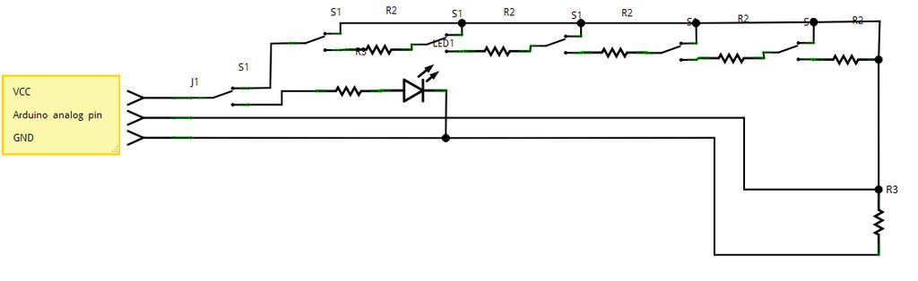
First you need to prepare the connecting wire. Take three wires, three pins and a piece of prototyping board with prepared lines of conductive material. I chose this type: the middle pin is analog value and others are VCC and GND.
Step 2: Prepare the box
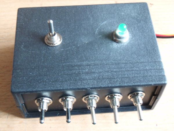
Take the front side of box and make five holes (i use my soldering iron for it 🙂 ) Put the switches to the holes.
Then take a top part of the box. Make there two holes. One for placing ON/OFF switch and one for LED (power indicator) .
Step 3: Connecting switche and resistors
As I said in step before it´s based on cascade of switches. To middle pin of first switch is connected the VCC power source. Left pin is connected to resistor, which goes to middle pin of next switch. The right pin is connected to wire, which is common for all switches (you can see on schematic). The resistor on last switch is connected to common wire.
6x switch
1x LED
1x 330 ohm resistor
For more detail: Analog reading box using an Arduino
- What is the primary purpose of this project?
This is a tutorial for making an analog reading box based on serial connected switches, not for playing melody. - How many switches are required for the build?
The project requires six switches to be installed in the plastic box. - Which pins are used on the prototyping board wire assembly?
The middle pin provides the analog value while the other two serve as VCC and GND. - How should the switches be wired together?
The switches are connected in a cascade where the left pin of one connects to a resistor leading to the next switch's middle pin. - What is the function of the common wire in the circuit?
The right pin of each switch connects to a single wire that acts as the common connection for all switches. - How do you prepare the plastic box for the components?
You must make five holes in the front side for the switches and two holes in the top part for the ON/OFF switch and LED. - Can this device be used to play musical melodies?
No, the article explicitly states this is only a tutorial for the box and not for playing melody.