Summary of An 8-Bit Waterfall using Arduino
This article demonstrates a cost-effective method to expand Arduino Uno's limited output pins using 74HC595N 8-bit shift registers. By connecting these chips via data, clock, and latch pins, users can control multiple outputs with just three Arduino pins. The author explains the cascading "waterfall" effect of linking multiple registers to create extensive I/O arrays, providing code examples and custom libraries (ShiftRegister and ShiftRegisters) to simplify pin management for both single and multi-chip configurations.
Parts used in the 8-Bit Waterfall Project:
- Arduino Uno
- 74HC595N 8-bit shift register
- LEDs
- Breadboard
So far my Arduino projects have all needed only a small number of output pins. In a previous post I talked about moving some of the logic off the Arduino and into other integrated circuits in order to free up pins on the Arduino. While this can help, I’m sure there will come a time when I’ll need more output pins then the Arduino Uno has to offer.

One solution would be to upgrade to an Arduino Mega as it has 54 digital output pins compared to the 14 digital pins on the Arduino Uno. The cost difference of around £15, however, doesn’t make this an attractive option. Fortunately there is a much cheaper way of adding extra output pins; 8-bit shift registers.
Whilst you don’t need to know the full details of how a shift register works an understanding of the basic principle will help. Essentially data is shifted into the chip one bit at a time using two pins; a data pin specifying the bit value and a clock pin that is triggered to show when the bit has been set. Once all the bits have been passed to the chip a third pin (known as the latch) is triggered at which point each bit is output on a separate pin of the chip. In the case of an 8-bit shift register (the 74HC595N for example) this allows us to control 8 pins (one for each bit) using just three pins on the Arduino (one each for data, clock and latch). In this way we can add five new digital output pins to an Arduino for just 70p (I got five chips for £3.50 from oomlout).
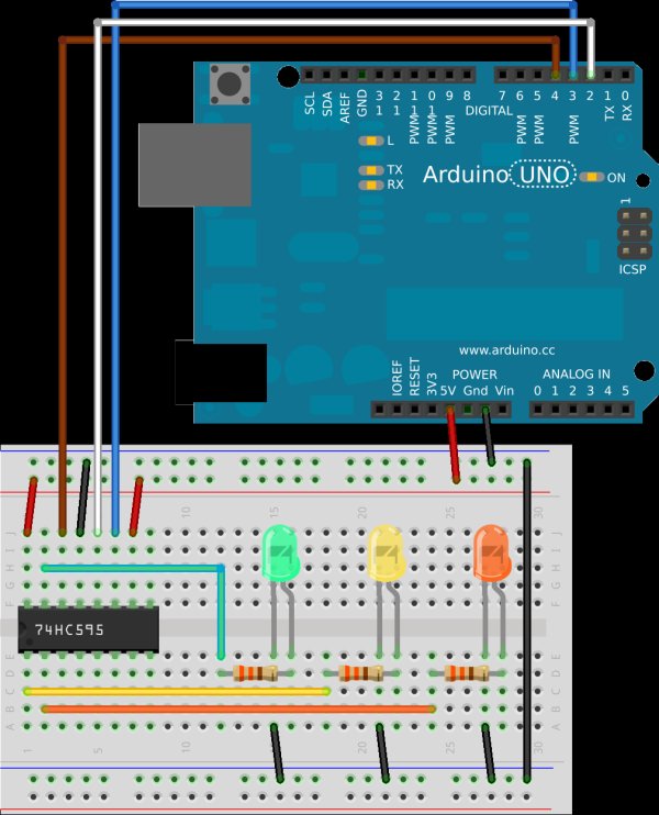
The 74HC595N is in fact such a common way to add extra pins to an Arduino that there is a simple tutorial already available, although I didn’t find this before I’d already wired up the circuit you can see to the left. Due to a shortage of space on my breadboard I only bothered to wire LEDs to three of the output pins, but it should be clear how to add LEDs to the other five output pins should you wish to. Also it’s worth noting that I haven’t needed to add a capacitor to the latch pin (a capacitor would ensure a smooth flow of power, but the Arduino on it’s own seems to work fine and I didn’t have any spare capacitors lying around). It’s important to make sure you pull the enable pin to ground otherwise you’ll find the lights flicker uncontrolably, if they come on at all.
Using this circuit I can cycle through all combinations of the three LEDs by writing the numbers 0 to 7 to the data pin. This works because we only need three bits to encode numbers 0 to 7 which will cause the relevant pins to go LOW/HIGH as appropriate. For those of you who aren’t so comfortable with binary the following table will help.
| Integer | Binary | |||||||
|---|---|---|---|---|---|---|---|---|
| 0 | 0 | 0 | 0 | 0 | 0 | 0 | 0 | 0 |
| 1 | 0 | 0 | 0 | 0 | 0 | 0 | 0 | 1 |
| 2 | 0 | 0 | 0 | 0 | 0 | 0 | 1 | 0 |
| 3 | 0 | 0 | 0 | 0 | 0 | 0 | 1 | 1 |
| 4 | 0 | 0 | 0 | 0 | 0 | 1 | 0 | 0 |
| 5 | 0 | 0 | 0 | 0 | 0 | 1 | 0 | 1 |
| 6 | 0 | 0 | 0 | 0 | 0 | 1 | 1 | 0 |
| 7 | 0 | 0 | 0 | 0 | 0 | 1 | 1 | 1 |
So to turn on the yellow LED we would write 2 to the chip or to turn on the green and orange LEDs we would write 5. The following simple sketch can be used to show that this does indeed work.
|
1
2
3
4
5
6
7
8
9
10
11
12
13
14
15
16
17
18
19
20
21
22
23
24
25
26
27
28
29
30
31
32
|
//the pins we are usingint latchPin = 2;int clockPin = 3;int dataPin = 4;void setup() { //set all the pins used to talk to the chip //as output pins so we can write to them pinMode(latchPin, OUTPUT); pinMode(clockPin, OUTPUT); pinMode(dataPin, OUTPUT);}void loop() { for (int i = 0; i < 8; i++) { //for each of the numbers 0 to 7... //take the latchPin low so the LEDs don't //change while we are writing data digitalWrite(latchPin, LOW); //shift out the bits shiftOut(dataPin, clockPin, MSBFIRST, i); //take the latch pin high so the pins reflect //the data we have sent digitalWrite(latchPin, HIGH); // pause before next value: delay(2000); }} |
Now while it is possible to control all 8 pins in the same way, sending a number from 0 to 256 to set the 8 pins isn’t really an ideal approach (unless there are a small fixed number of output you need at which point you could define a constant for each of them and write those out as necessary). Ideally what we want to be able to do is to simply set each pin as LOW or HIGH without changing the state of any of the other pins. Fortunately this is easy to do using the Arduino bitSet and bitClear functions. For example, take this snippet of an Arduino sketch.
|
1
2
3
4
5
6
7
8
9
10
11
12
13
14
15
16
17
|
//assume all pins start out LOWbyte state = B00000000;//set the third pin high, i.e.//state = B00000100bitSet(state, 2);//take the latchPin low so the LEDs don't//change while we are writing datadigitalWrite(latchPin, LOW);//shift out the bitsshiftOut(dataPin, clockPin, MSBFIRST, state); //take the latch pin high so the pins reflect//the data we have sentdigitalWrite(latchPin, HIGH); |
Most of this code is from the previous sketch, the interesting bit is line 6. Here we set the 2nd bit (which forces it HIGH). Remember that, as in most computer situations, numbering starts from 0, so this sets the third pin HIGH, which given our example circuit would turn on just the orange LED. The bitClear function works in exactly the same way, but pulls the bit LOW rather than HIGH. It’s reasonably straightforward to convert these ideas into a couple of functions which make working with a shift register easy. Partly as a learning exercise, but mostly as I think it will be useful, I’ve actually created a new Arduino library called ShiftRegister so that I can easily include the functionality in any sketch where I need it. You can grab the library from my subversion repository. The library includes the following example sketch which assumes the same circuit we’ve already looked at.
|
1
2
3
4
5
6
7
8
9
10
11
12
13
14
15
16
17
18
19
20
21
22
23
24
25
26
27
28
29
30
31
32
33
34
35
36
|
/** * ShiftRegister * Copyright (c) Mark A. Greenwood, 2012 * This work is licensed under the Creative Commons * Attribution-NonCommercial-ShareAlike 3.0 Unported License. * To view a copy of this license, visit **/#include <ShiftRegister.h>ShiftRegister sr(4,3,2);void setup() { //there is nothing to do}void loop() { sr.setPin(0, HIGH); delay(2000); sr.setPin(1, HIGH); delay(2000); sr.setPin(2, HIGH); delay(2000); sr.setPin(0, LOW); delay(2000); sr.setPin(1, LOW); delay(2000); sr.setPin(2, LOW); delay(2000);} |
If you run this sketch on the Arduino you’ll see that it simply lights up the three LEDs starting with the green one, and then turns them off again in the same order. I’ve tried to make it easy to configure the libary and as you can see in line 12 you can specify which pins you are using on the Arduino. By default calling setPin with two arguments automatically causes the changes to be sent to the shift register. If you want to send a number of changes at once then you can as this snippet shows.
|
1
2
3
4
5
6
|
//set pins 0 and 2 highsr.setPin(0, HIGH, false);sr.setPin(2, HIGH, false);//push the new values to the shift registersr.sync(); |
By this point you may be wondering why I called this post “An 8-Bit Waterfall”, well the answer lies in one of the pins of the 74HC757N which we haven’t looked at yet; the overflow pin.
When you have shifted in 8 bits the register is full. Shifting in a 9th bit causes the first bit you pushed in to be pushed out on the overflow pin. So just like water cascades down a waterfall so data can cascade down a series of shift registers. The circuit on the left shows how we can link two 8-bit shift registers together to give us 13 new digital output pins for just £1.40.
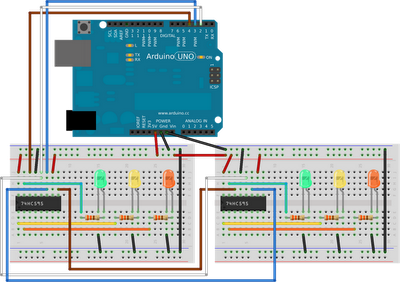
You can see the waterfall in action by running the example ShiftRegister sketch using this new circuit. What you’ll notice is that the second set of LEDs is always one step behind the first set. To make actual use of the second register we need a new version of the library which can handle multiple registers. My imagination failed me and so the new library is called ShiftRegisters! You can also grab this version of the library from my subversion repository. This library includes the following example sketch.
|
1
2
3
4
5
6
7
8
9
10
11
12
13
14
15
16
17
18
19
20
21
22
23
24
25
26
27
28
29
30
31
32
33
34
35
36
37
38
39
40
41
42
43
44
45
46
47
48
49
50
51
52
53
54
|
/** * ShiftRegisters * Copyright (c) Mark A. Greenwood, 2012 * This work is licensed under the Creative Commons * Attribution-NonCommercial-ShareAlike 3.0 Unported License. * To view a copy of this license, visit **/#include <ShiftRegisters.h>ShiftRegisters sr(4,3,2,2);void setup() { //there is nothing to do}void loop() { sr.setPin(0, HIGH); delay(2000); sr.setPin(1, HIGH); delay(2000); sr.setPin(2, HIGH); delay(2000); sr.setPin(8, HIGH); delay(2000); sr.setPin(9, HIGH); delay(2000); sr.setPin(10, HIGH); delay(2000); sr.setPin(0, 0, LOW, true); delay(2000); sr.setPin(0, 1, LOW, true); delay(2000); sr.setPin(0, 2, LOW, true); delay(2000); sr.setPin(1, 0, LOW, true); delay(2000); sr.setPin(1, 1, LOW, true); delay(2000); sr.setPin(1, 2, LOW, true); delay(2000);} |
This example simply turns the six LEDs on and then off in sequence, but shows that there are two ways of addressing each pin. Firstly we can simply address each pin in turn; so the pins on the first chip are 0 to 7 and on the second 8 to 15, etc. Or we can specify pin 0 to 7 for each chip (numbered 0 and 1). Note that if you use the second approach you have to use the four argument version of the method and specify if you want sync called for you or not (this is because the arguments preclude me producing a three argument version as the compiler gets confused). The second method will be slightly quicker as there is a little less maths involved, although which you find most intuitive is up to you. Note also that line 12 now includes (as the last argument) the number of shift registers we have in sequence. If you don’t specify the number then the library assumes there are 32 registers giving you 256 pins in total (or 233 new pins). Given the way the library is written (the pin variable is a byte) 32 registers is also the maximum it can support.
You could use the second library with just one shift register if you wanted to, but I’ve kept the two versions separate in case code size is an issue as the second version is larger and there is no point including extra code within a sketch if it isn’t needed.
So for my initial investment of £3.50 I can add an additional 37 digital output pins to my Arduino Uno. Of course you can’t use these pins for input as you could with the extra pins on an Arduino Mega, but you can also add extra input pins in a similar way.
Source : An 8-Bit Waterfall using Arduino
- How many digital output pins does an Arduino Mega have compared to an Uno?
An Arduino Mega has 54 digital output pins while an Uno has 14. - Can you add extra output pins without buying a new board?
Yes, you can add extra pins cheaply using 8-bit shift registers like the 74HC595N. - Which pins on the Arduino are required to control one shift register?
You need three pins on the Arduino for data, clock, and latch. - What happens if the enable pin is not pulled to ground?
The lights will flicker uncontrollably or may not come on at all. - How do you turn on a specific pin without changing others?
Use the Arduino bitSet and bitClear functions to modify the state byte. - What is the overflow pin used for in this project?
It allows data to cascade from one shift register to another when the first is full. - How many new digital output pins can be added with five shift registers?
You can add 37 additional digital output pins to the Arduino Uno. - Are the extra pins created by shift registers usable for input?
No, you cannot use these pins for input as you could with an Arduino Mega.