Summary of Amazon Alexa Enabled USB Fan
This project modifies a Comfort Zone USB fan to be controlled by Amazon Alexa using an ESP8266 Wi-Fi module (Wemos D1 mini). By replacing the fan's power switch with a MOSFET controlled by the ESP8266 running fauxmoESP firmware, the fan can be turned on or off with voice commands via Alexa and automatically turns off after a set time. The ESP8266 and MOSFET are fitted inside the fan’s battery compartment, requiring soldering and wiring adjustments. Detailed instructions cover disassembly, wiring, software setup, and integration with Alexa for smart home control.
Parts used in the Amazon Alexa Enabled USB Fan project:
- Comfort Zone Oscillating Desk USB Fan (with battery compartment)
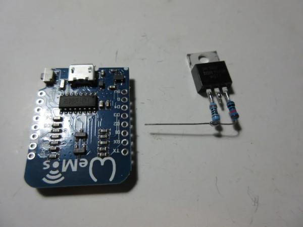
- ESP8266 Wi-Fi Module (Wemos D1 mini)
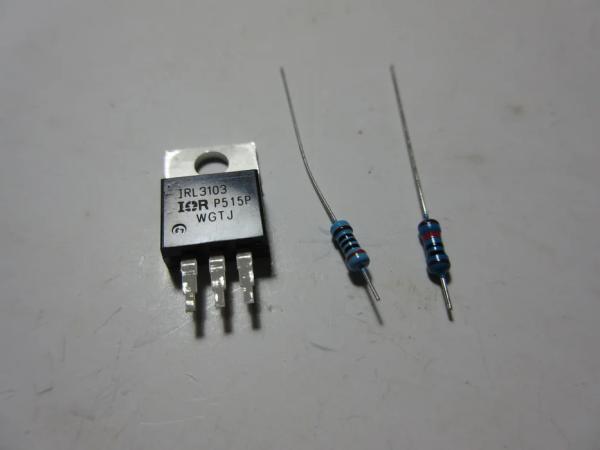
- IRL3103PbF N-Channel Logic Level MOSFET
- 300 Ohm resistor
- 10K Ohm resistor
- Wires (various lengths, including a 4-wire ribbon cable)
- Solder and soldering tools (iron, wick)
- Hot glue and hot glue gun
- Micro USB cable
- Tools: Hobby knife, screwdrivers, tweezers, wire strippers
- Software: Arduino IDE with ESP8266 libraries and fauxmoESP project
Amazon’s Alexa is cool. USB fans are cool. Alexa enabled USB fan, even cooler. This fan turns on with a voice command to an Amazon Alexa device, “Alexa, turn [insert your name here]’s fan on”. The fan is also set to turn off automatically after 45minutes (adjustable through code).
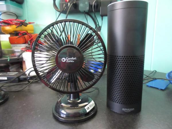
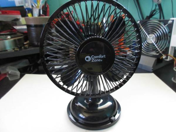
The weather has been hot lately and my kids wanted a fan in their room to cool them off at night when they go to sleep. We used a stationary Vornado fan but the fan was way too loud (even at the lowest setting) and kept them up. I stumbled across these plastic Comfort Zone desktop USB fans at my local hardware store on sale for $11 each (also available on Amazon). The fans are fairly quiet and strong enough to provide a pleasant breeze. The fans are perfect except I had to remember to turn them off.
I have a bunch of ESP8266 Wi-Fi modules and read about the fauxmoESP project. That gave me the idea to control the fans with Amazon’s Alexa. Initially I thought about making a small hub that used one module with 2 USB ports, but that seemed like a lot of work designing and printing an enclosure and I would have to order female USB ports. The simpler method is to stick the ESP8266 module in each fan. This ends up using more modules and USB chargers but I completed this project in a day for 4 fans (one for each member of the family).
These instructions are for the Comfort Zone fans, but I’m sure that similar USB fans can be modified. My guess is that any fan with optional battery power would be a great candidate since the ESP8266 would fit in the battery compartment.
Step 1: Materials, Tools, Supplies and Software
Materials
- USB Fan with battery compartment (Comfort Zone Oscillating Desk Fan)
- ESP8266 Module (Wemos D1 mini)
- Logic Level N-Channel Mosfet (IRL3103PbF)
- 300 Ohm Resistor
- 10K Ohm Resistor
- Wire
Tools
- Hobby Knife
- Hot Glue Gun
- Micro USB Cable
- Screw Driver
- Soldering Iron
- Tweezers
- Wire Strippers
Supplies
- Solder
- Solder Wick
- Hot Glue
Software
- Arduino IDE
Notes:
Almost any USB fan could be used for this project as long as there is room to fit the ESP8266 module. A fan with a 4AA battery compartment will fit a Wemos D1 mini. If using another fan, you would need to figure out the circuit of the fan and basically replace the switch with the Wemos D1 mini.
I chose the Wemos D1 mini as it is an inexpensive and an easy ESP8266 module to use. The board contains everything you need to get started right away. It has a USB connection to connect to your computer and a decent LDO voltage regulator that you can connect USB power to.
I used an IRL3103 N-Channel MOSFET because it fully turns on with 3.3V on the gate, on resistance is very low, capable of 64A, and works nicely with 5V. I know the current rating is overkill, probably only need around 750mA, 200mA for the ESP8266, 400mA for the fan, and some leeway. If you choose another MOSFET make sure it is similar and able to handle the power requirements.
Step 2: Fan Modification Wiring
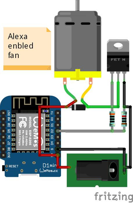
The diagrams show the fan’s original wiring (minus the connectors to the motor and front PCB that has the power switch/speed select) and the modified wiring.
Basically the modification is just replacing the original power switch with an ESP8266 module and MOSFET as a switch.
As for values for the resistors and MOSFET, I pieced what I could understand from reading electronics posts and blogs. I am a software developer and dabble in electronics as a hobby so please don’t scream at me at why use that or don’t need it. I do welcome suggestions and improvements if you have any.
I chose 300 ohm for the gate resistor after reading somewhere that even though the gate is suppose to be high impedance, there is chance that it goes low during a transition. The 300 ohm should limit current at the 12mA I/O max of the ESP8266.
The 10K resistor to ground is what most say is good enough to discharge the gate. Works for me so why not.
I’m not sure if there is already a flyback diode somewhere up the fan assembly. I’m guessing there isn’t any. So I reuse the diode that was meant to protect the batteries from the USB power as a flyback diode across the fan motor. Speaking of that diode, what protects the USB power? I guess they expect the USB to protect itself.
Like I said, I’m a software developer, so I welcome suggestions and improvements for the electronic parts.
Step 3: Program the ESP8266

Program your ESP8266 module first.
Install the ESP8266 libraries for the Arduino IDE.
Download the project fauxmoESP from Bitbucket. Also download all the dependencies for fauxmoESP. I chose fauxmoESP for its simplicity and ease of use. Aside from the necessary ESP8266 library setup, you just need 4 lines of code to enable Alexa to turn on and off something.
Download the Arduino project files ESP8266AlexaEnabledUsbFan from GitHub.
The Arduino project is in the folder src/ESP8266AlexaEnabledUsbFan/. You can double-click on ESP8266AlexaEnabledUsbFan.ino to open the project in the Arduino IDE.
There are a few lines of code that will need updates.
//#define DEBUG // uncomment to print to Serial output
This line enables/disables debug statements to serial out. Uncomment if you run into problems. The debug statements tell you if you connect to your Wi-Fi and the IP of the module, and if the module responds to Alexa. For now, uncomment the line by remove the beginning two slashes “//”.
#include <MyCredentials.h> // contains my credential information ...
You can create a MyCredentials.h file and define the symbols HOME_WIFI_SSID and HOME_WIFI_PASSWORD or remove this line and hardcode your SSID and password further in the program for WiFi.begin(). *Note: To be safe and save yourself from frustration, treat SSID as case sensitive. I’m not sure if my router or the ESP8266 module is the one that is picky about it. I could not connect to my Wi-Fi when I used all lower case when my SSID had capital letters in a few places. I had to match the SSID exactly.*
#define DEVICE_NAME "Daddy's fan" // name used for Alexa command ...
This line defines the name you will use for the Alexa on/off command. As coded, you would say “Alexa, turn Daddy’s fan on”. Change to something meaningful for your fan.
#define FAN_ON_DURATION 2700000 // 45mins = 2700000ms ...
This line defines how long the fan will stay on in milliseconds when turned on by Alexa. Change to a time that suits you.
// setup static IP as this cuts down on time trying to obtain an IP through DHCP
IPAddress espIP(192, 168, 1, 30);
IPAddress gateway(192, 168, 1, 1);
IPAddress subnet(255, 255, 255, 0);
These set of lines are to setup the IP address of the ESP8266 module. You want to set a static IP as Alexa remembers your device by IP. So if the IP changes, you will need to rediscover the device before you can control it again. Read your Wi-Fi’s manual on how to set a static IP connection and enter the correct settings.
WiFi.begin(HOME_WIFI_SSID, HOME_WIFI_PASSWORD);
Finally, if you do not want to make MyCredentials.h file. You will need to enter your Wi-Fi information here.
Compile and flash the program to your ESP8266 module via a micro USB cable.
Open the Arduino IDE Serial Monitor and reset the module. You should see the connection to your Wi-Fi. If not, then the Wi-Fi credentials and/or IP settings are incorrect. *Note: SSID might be case sensitive as I mentioned earlier.*
Keep the module attached to you computer and the Arduino IDE running for the next step.
Step 4: Discover Device
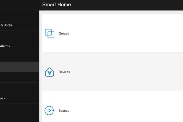
Open and login to the Amazon Alexa application at https://alexa.amazon.com.
Click on Smart Home in the left pane.
Click Devices in the right pane.
Click on Discover.
You should see your device name show up as a Wemo switch. As you can see, I made 4.
Command Alexa to turn on and off your fan. You should see debug statements in the Serial Output window of the Arduino IDE.
If the module responds correctly to Alexa, comment the debug statement and re-flash the program to the ESP8266 module. The module does not need to send serial output since you will embed it in the fan.
Now that our module is setup, we will move onto modifying the USB fan.
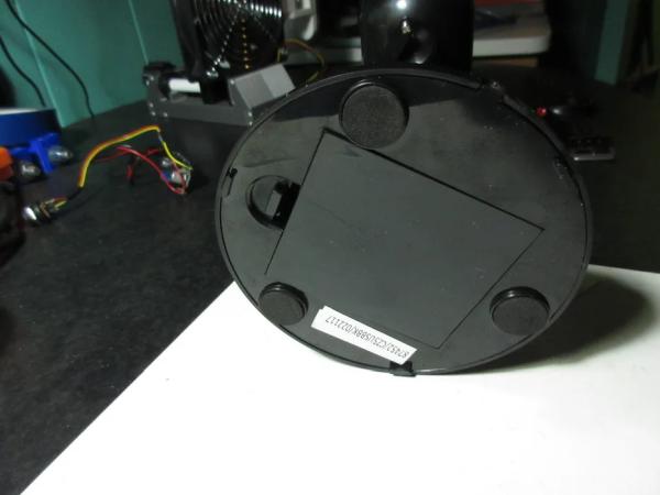
Step 5: Remove Switch Knob
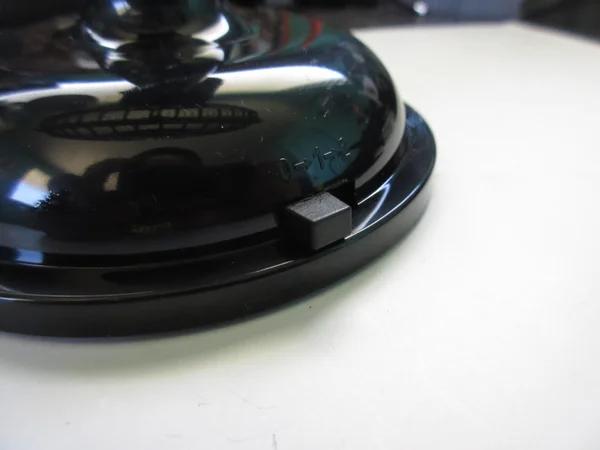
At the base of the fan is the power switch. You will need to pull off the plastic knob as it does not slip into the slit when you remove the bottom.
Step 6: Remove Bottom Screws
Place the fan on its side. Best to place with the fan face down. The plastic structure of the fan doesn’t seem strong. With the fan face down, you don’t stress out the neck as much.
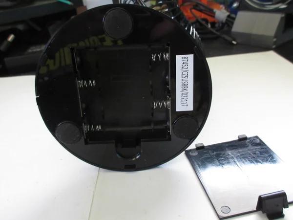
Remove the battery cover and keep it close.
Carefully remove the circular foam pads to keep the sticky stuck to it. Best to slowly lift the pad from all around instead of just tearing from one side. Stick the removed pads to the inside of the battery cover. The battery cover makes a great temporary holding place for the pads.
Remove the screws that were hidden under the pads and store them somewhere safe. The screws are small and desktop gremlins love sneaking away with them.
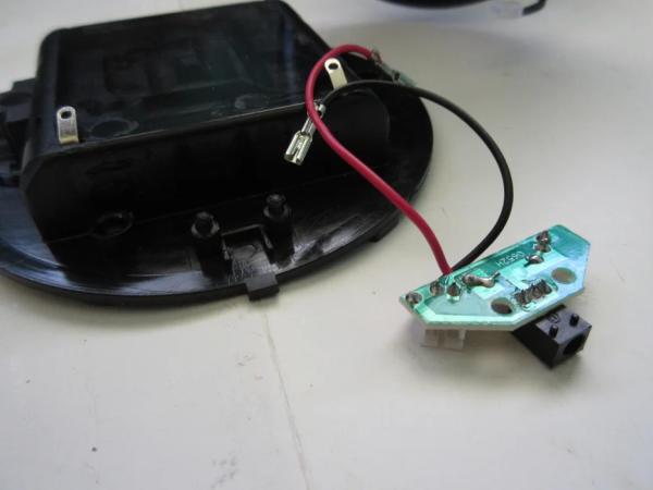
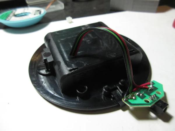
Step 7: Disconnect Connectors
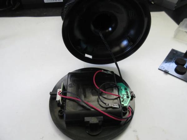
Remove the bottom from the fan.
The rear of the fan has a PCB with a DC jack and two connectors. One connector (with red and black wires) leads to the switch in front. The other connector (two black wires) connects to the fan motor.
Disconnect the two connectors.
Step 8: Remove Battery Connections
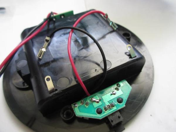
Remove the two connections from the rear PCB to the battery terminals.
Step 9: (Optional) Remove Power Switch
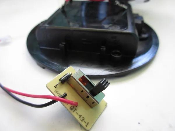
I removed the power switch because the fan will turn on and off with Alexa. Also, I don’t care for two speeds, I just want max speed.
The switch PCB pulls straight out.
Oh another reason for removing the switch is to prevent my wife and kids complaining the switch doesn’t do anything. So I rather just remove it completely.
Step 10: Unmount Rear PCB
Unmount the rear PCB.
Some models have the PCB mounted with screws and others snapped in. My blue fan had screws while the three other black fans snapped onto posts.
Step 11: Remove Battery Terminals
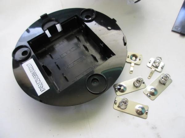
Straighten the battery tabs sticking through from the battery compartment.
Flip the bottom over and remove all the battery springs, connectors, and terminals.
Step 12: Solder Flyback Diode
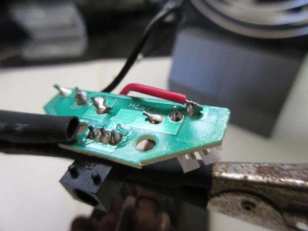
I’m not sure of the internals of the fan if there is a flyback diode or not. I’m guess there is none considering this fan is cheapy.
We can reuse the battery protection diode as the flyback diode. The great part is that the diode is already half-way in the right place and we can reuse a wire already connected to it.
You will need to connect the red wire that used to connect to the batteries to the ground side pin of the connector to the motor. The right most solder pad if you are looking at PCB with DC jack facing you on the bottom of the PCB.
Cut the red wire to length a little past the connector.
Strip the end and tin.
Solder the wire to the connector’s pin.
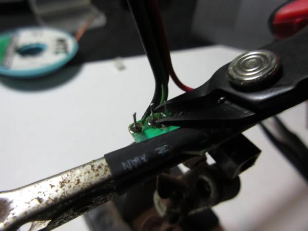
Step 13: Remove Switch Connector & Last Battery Wire
Use a soldering iron to remove the black wire that used to connect to the batteries.
Do the same for the connector that was used to connect to the front PCB.
Use solder wick to clean the solder pad and holes so that you can use them in the up coming steps. This will make soldering in wires easier.
Step 14: Widen Battery Terminal Hole
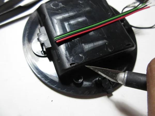
Widen the left hole (when looking at the bottom facing the rear) that had a battery terminal sticking out of. Widen the hole big enough that you can fit 4 of the wires you will use to connect the rear PCB to the ESP8266 module.
Cut your wires to a length of about 6 inches each. I happen to have a nicely colored 4-wire ribbon cable. Two negative wires (black), one positive (red), and one for the motor’s negative connection to the MOSFET drain pin(green).
Step 15: Strip and Tin Wires
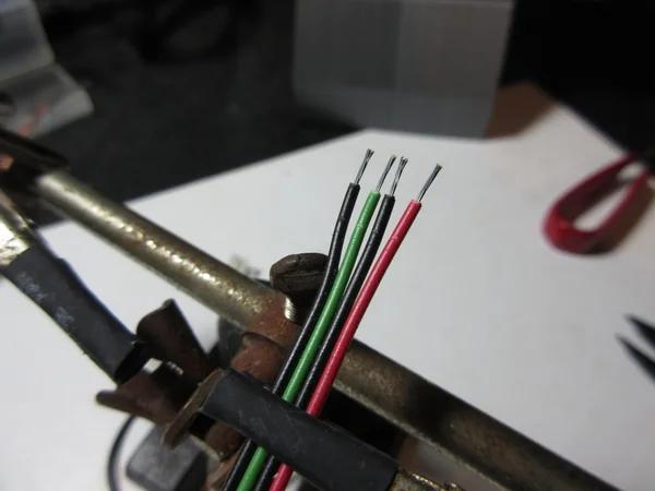
Strip and tin one end of your wires.
Step 16: Soldering Wires to Rear PCB
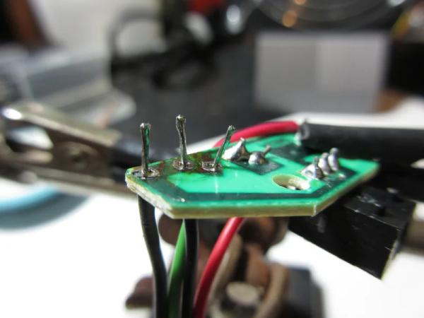
Stick your wires that will be used to connect to ground in the two left most holes. Left-most hole used to have the black wire connected to the batteries. The next hole was the left pin of the connector that used to connect to the front PCB.
Stick your motor wire to the right pin of the connector that used to connect to the front PCB.
Solder the wires in place.
Step 17: Solder Power Wire to Rear PCB
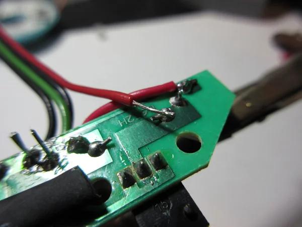
Solder the last wire for power to the diode leg connected to the positive input of the DC jack (I found this the easiest spot to solder to). This would be third solder spot from the right.
Step 18: Trim Excess
Trim any excess wire you have after you have soldered the 4 wires.
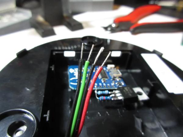
Step 19: Insert Wires Into Battery Compartment
Insert the 4 wires you just soldered to the rear PCB through the hole you widened earlier.
Pull about half length of the wires into the battery compartment.
Remount the rear PCB.
Pull the slack in the wires into the battery compartment. The base has some clearance above the bottom so you don’t have to worry about completely removing all slack. There is some wiggle room.
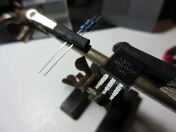
Step 20: Prepare MOSFET and Resistors
To make the ESP8266 module and components fit in the battery compartment you will need to trim the legs of the MOSFET.
I trimmed the MOSFET legs about 1mm away from the body where the legs became thinner.
I trimmed one side of the resistors to about 3mm.
Step 21: Tin MOSFET Legs
Tin the legs of the MOSFET. Try to leave a smidge of solder on the leg. This will make connecting the resistors and wires easier.
Tin the short legs of the resistors.
Step 22: Solder 10K Resistor to Source Pin
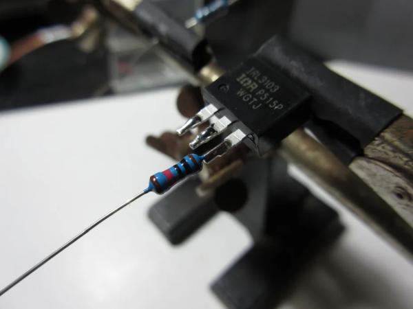
Solder the short leg of the 10k ohm resistor to the source pin of the MOSFET.
Since the MOSFET leg has some solder on it and the resistor leg is tinned, put the two together and heat with a tinned iron. The MOSFET and resistor should solder together quickly and nicely.
Step 23: Solder 300 Ohm Resistor to Gate Pin
Solder the 300 ohm resistor to the gate pin. Just like how you did in the last step.
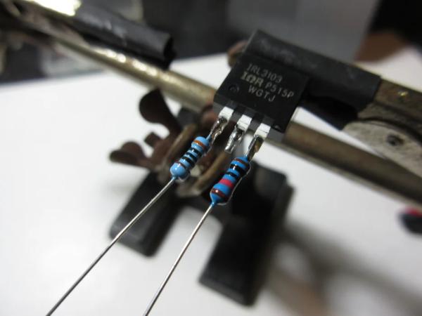
Step 24: Connecting Resistors Together
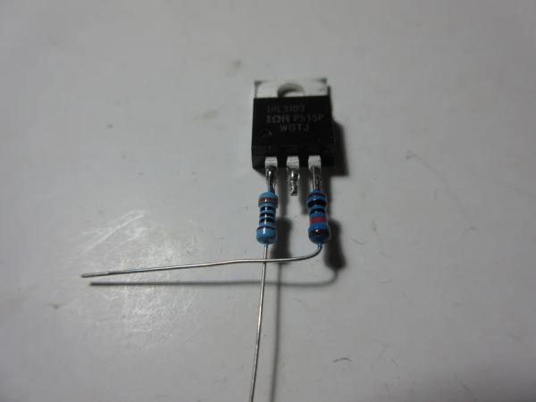
Lay the MOSFET with the ground plate side down.
Bend the leg of the 10K resistor at a right angle towards the 300 ohm resistor.
Join the resistors together by wrapping the leg of the 300 ohm resistor around the leg of the 10K resistor where they intersect a few times. Cut the excess leg off of the 300 ohm resistor.
Solder the joint.
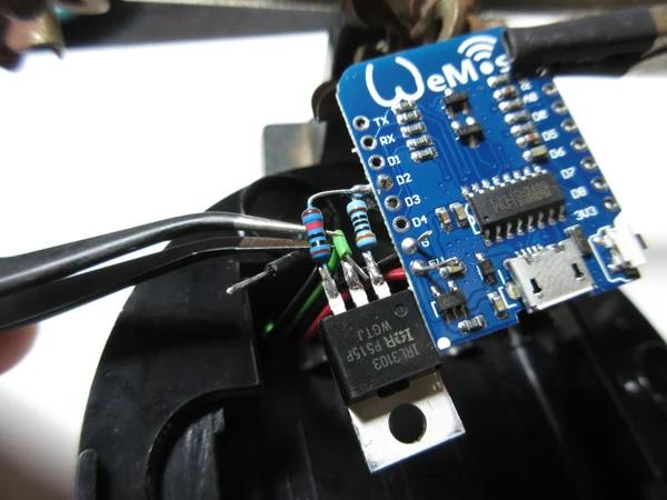
Step 25: Connect MOSFET to ESP8266 Module
Place the ESP8266 module with the metal casing side down.
Place the MOSFET ground plate down to the to the right of the ESP8266 module.
Insert the leg of the 10K resistor into the D2 hole from the bottom. The leg should be stick out of the module on the side of the USB connector. Try to get the MOSFET as close as possible to the module.
Solder the resistor in place and cut off the excess.
Note: Handle this component by the ESP8266 module so that you do not stress break the resistor leg.
Step 26: Cut Wires to Length
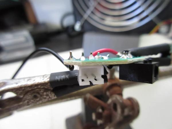
Place the module in the battery compartment (remember to only handle the ESP8266 and not the MOSFET).
I placed the module on the far side of where the wires enter (see picture).
Trim the wires to a length that can reach the module but not too short, you want about 2-3mm excess length so that you can trim the ends for leads).
Step 27: Strip and Tin
As usual, strip and tin the end of the wires to make soldering easier.
Step 28: Solder 5V and GND
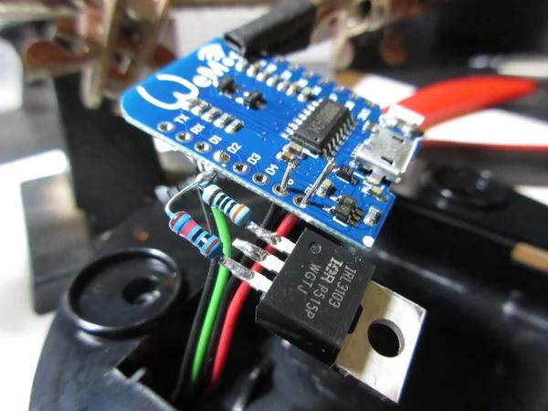
Insert your positive wire lead into the 5V hole and your negative wire into the GND hole.
Solder in place.
Step 29: Solder Motor Wire
This step is easier done with tweezers.
Solder the motor wire to the drain pin of the MOSFET. As you did with the resistors earlier, as long as the leg and wire lead have solder on them, a quick touch of the soldering to the two will connect them together.
Step 30: Solder Ground Wire to MOSFET
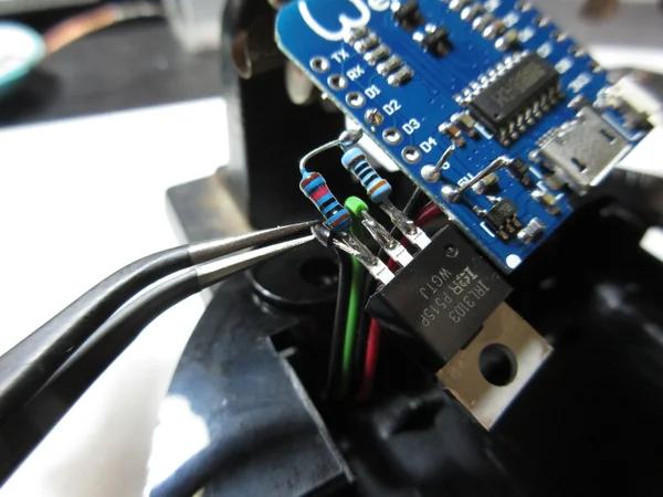
Solder the final wire that should be the ground wire to the source pin of the MOSFET. This pin has the 10K resistor attached to it.
Step 31: Hot Glue Gun MOSFET
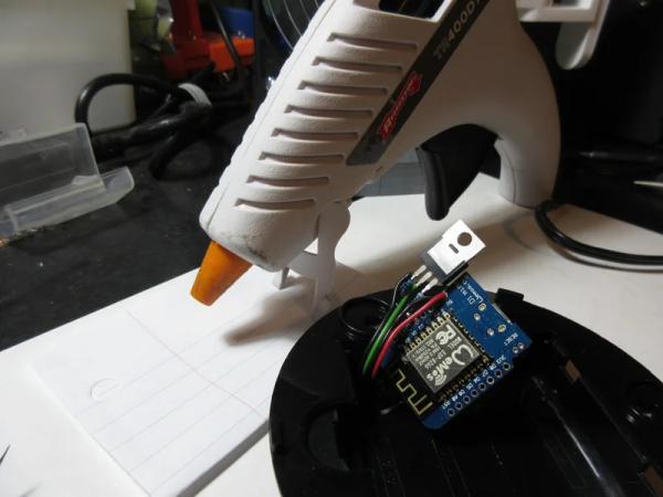
Use a hot glue gun to hold the MOSFET in place. A drop or two globbed on the side that has the metal casing should be enough to hold the MOSFET.
The reason I held off doing this step for last is that I’m terrible with a hot glue gun. I didn’t want glue flowing over the 5V and GND pads of the ESP8266 module before the wires are soldered in place.
With the MOSFET glued in place you don’t have to worry about stressing the connecting resistor leg.
Step 32: Test Run
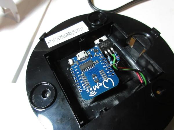
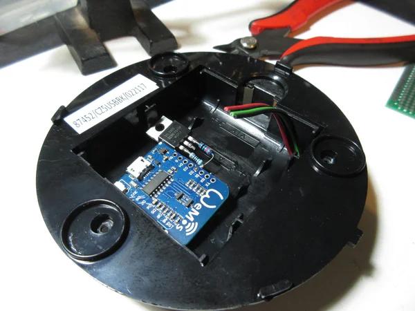
Place the ESP8266 assembly into the battery compartment and place the battery cover back on.
Place the top of the fan close enough that you can connect the fan motor to the rear PCB. Reconnect the fan motor.
Make sure the top of the fan is upright.
Plug in the USB cable and connect to a USB charger that is capable of delivering at minimum 600mA.
Speak your Alexa command. The fan should turn on. If not, check your connections and make sure you flashed the ESP8266 correctly.
Step 33: Put Fan Back Together
Align the top and bottom correctly and screw back together.
Return the foam pads to theirs spots covering the screws.
Step 34: Personalize
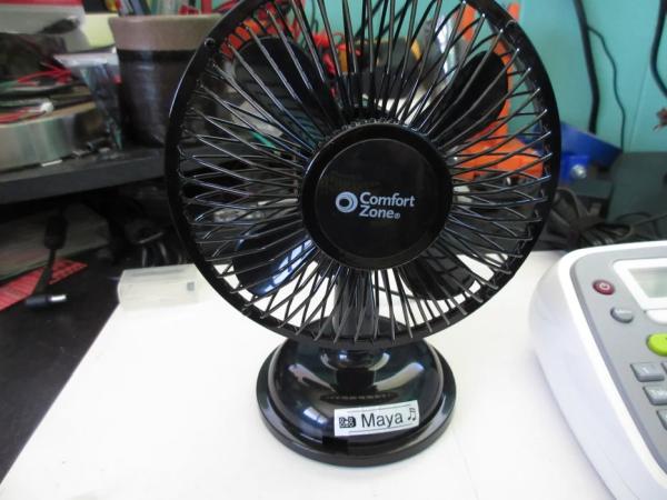
Personalize the fans so you know the name of the fan. Useful if you have many fans. I just used a simple label maker to put the name of the fan.
Source: Amazon Alexa Enabled USB Fan