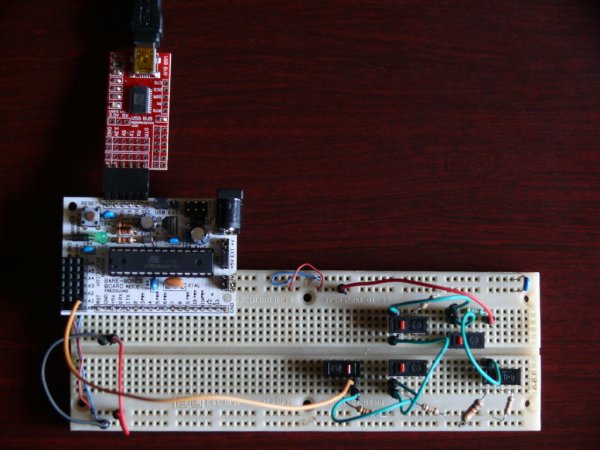
I’m starting a project to build a clock that will display multiple timezones (And a bunch of other stuff too), and I need some inputs to set the time and manage the menu options. Since I’d already done the research (Albeit a year ago..) I figured I’ll use the same setup to create a 4 or 5 button panel to navigate the settings and change the relevant values.
What I found though is that the original Instructable was a good proof of concept, but it wasn’t good enough to put in practice. After working on this the whole night I now have a more practical solution.
Step 2: The theory – A quick recap
I suggest that you read step 2 and step 3 of the previous Instructable for the details, but if you’re lazy (Uhmm, busy I mean), I’ll give you a quick recap.
The usual way to read a button is to hook it up to a digital input pin and 5V. When you press the button, the input pin is connected to 5V and you can read a logical HIGH on the pin.
For the Arduino’s analog pins, you read a value between 0 and 1023 based on the voltage you have on the pin. If there’s 0V, you read a 0, and if there’s 5V, you read 1023. Every voltage in between will return a proportional value based on the actual voltage.
From this, it follows that it is possible to connect multiple buttons to analog pin if you can get each of them to connect a different voltage to the analog pin.
As it turns out, this is very simple. You just need to set up a different voltage divider for each button. I’ll show you how.
If you look at the circuit, R1 acts as a pulldown resistor when the buttons are open, but when (for example) the S4 button closes, the current flows from 5V, through R5, through the button, through R1 and to ground. The IO Pin will measure the voltage between S4 (or R5) and R1 – AKA a voltage divider is formed by R1 and R5. By using Ohm’s law, we can calculate that we’ll read about 2.75V on the IO pin or about 562.
PS: If any of this is unclear, you should really read the previous Instructable – I go into a lot more detail. Also have a look at the above link to the Wikipedia page on voltage dividers.
Parts list
1 x 100K Resistor (Brown Black Yellow)
1 x 1K Resistor (Brown Black Red)
1 x 10K Resistor (Brown Black Orange)
1 x 22K Resistor (Red Red Orange)
1 x 33K Resistor (Orange Orange Orange)
1 x 68K Resistor (Blue Gray Orange)
5 x Push button switches
A Breadboard
Some wires to connect it all
For more detail: Accessing 5 buttons through 1 Arduino pin

