Most of industrial robots are still programmed using the typical teaching process, through the use of the robot teach pendant. In this paper is proposed an accelerometer-based system to control an industrial robot using two low-cost and small 3-axis wireless accelerometers. These accelerometers are attached to the human arms, capturing its behavior (gestures and postures). An Artificial Neural Network (ANN) trained with a back-propagation algorithm was used to recognize arm gestures and postures, which then will be used as input in the control of the robot. The aim is that the robot starts the movement almost at the same time as the user starts to perform a gesture or posture (low response time). The results show that the system allows the control of an industrial robot in an intuitive way.
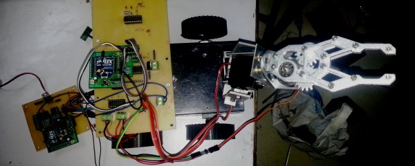
However, the achieved recognition rate of gestures and postures (92%) should be improved in future, keeping the compromise with the system response time (160 milliseconds). Finally, the results of some tests performed with an industrial robot are presented and discussed. Guys in this project we are going to use two communication standards to control our robot one is xbee for gripper motion control in three axis and GSM to control mobility of drone. In this project we learn about XBEE standards, types, its configuration, interfacing with microcontrollers, DTMF decoding, DTMF signal processing, basic robot control, motor driver circuits, servo motor control, PWM signal generation.
Collect this all
 1)Flex Sensor:
Flex is a resistive sensor which changes its resistance according to bend. simple two pin sensor for testing it guys just put your multimeter in resistance mode and feel change in resistance. But we cannot use this sensor as it is so we need some kind of driver circuit………………… ya just an voltage divider bias circuit simple one resistor of 10K and connecting wires. connections are very simple follow schematic.
2) Accelerometer ADXL 335:
ADXL 335 is a board come with ADXL 335 ic and all supporting components which required for conditioning of a signal. It is 5 pin device again depend on manufacturing varies in pin configuration. In our case we gona use only four pins VCC, GND, X axis and Y axis. Again follow schematic for connections.
3) XBEE S1:
It’s up to you which xbee module is to buy. Normally three types are available in market S1, S2, S1 PRO, configuration method for all xbee modules are almost same, we program it in AT command mode follow XBEE configuration tutorials. Use xbee shield to interface xbee with Arduino or AVR microcontroller for connection please check schematic.
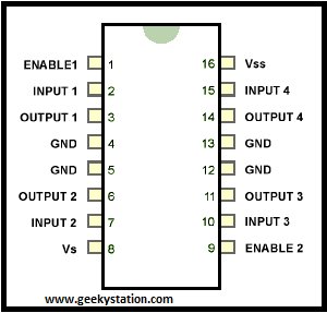
4) Motor Driver L293D:
To control two DC motors we required only one chip of L293D . Connections are simple do same as given in Circuit Diagram. We also connect Four motors with same connection tow motors at each side. For more details follow datasheets.
5) Microcontroller:
Here we are using Arduino UNO R3 but guys u have an option of making your own breakout board using Atmega 328, 168, 8 According to your application but don’t forgot to burn bootloader without that u never gona burn any code from Arduino board (To burn bootloader in blank chip please follow our link HOW TO BURN BOOTLOADER IN ATMEGA 328) next for connections refer circuit diagram. If you are using Atmega 328/168/8 with own made board then follow this pin mapping and compare it with standard Arduino.
Tx Code
// www.geekystation.com
// gesture control robotic gripper DTMF controlled drone
//program :- for transmitter
int sen0 = A0;
int sen1 = A1;
int sen2 = A2;
void setup()
{
Serial.begin(9600);
}
void loop()
{
int val0 = map(analogRead(sen0), 260, 450, 100, 210);
Serial.print(val0);
int val1 = map(analogRead(sen1), 260, 450, 100, 210);
Serial.print(val1);
int val2 = map(analogRead(sen2), 450, 620, 100, 210);
Serial.print(val2);
delay(50);
}
Rx Code
// www.geekystation.com
// gesture control robotic gripper DTMF controlled drone
//program :- for reciever
#include
int servo0Pin = 6;
int servo1Pin = 7;
int servo2Pin = 8;
Servo myservo0;
Servo myservo1;
Servo myservo2;
int val0=2;
int val1=3;
int val2=4;
int val3=5;
int buttonState0 = 0;
int buttonState1 = 0;
int buttonState2 = 0;
int buttonState3 = 0;
int out0=9;
int out1=10;
int out2=11;
int out3=12;
int d,i,n;
int u,v,w;
int dlast,nlast,ilast;
void setup()
{Serial.begin(9600);
pinMode(out0, OUTPUT);
pinMode(out1, OUTPUT);
pinMode(out2, OUTPUT);
pinMode(out3, OUTPUT);
pinMode(val0, INPUT);
pinMode(val1, INPUT);
pinMode(val2, INPUT);
pinMode(val3, INPUT);
myservo0.attach(servo0Pin);
myservo1.attach(servo1Pin);
myservo2.attach(servo2Pin);}
void loop()
{
while(Serial.available() == 0);
//int data = Serial.read() – ‘0’;
byte a= Serial.read();
byte b= Serial.read();
byte c= Serial.read();
byte f= Serial.read();
byte g= Serial.read();
byte h= Serial.read();
byte k= Serial.read();
byte l= Serial.read();
byte m= Serial.read();
d= (c-48) + (b-48)*10 + (a-48)*100;
d = map(d, 100, 210, 20, 130);
d = constrain(d, 20, 130);
i= (h-48) + (g-48)*10 + (f-48)*100;
i = map(i, 100, 210, 20, 130);
i = constrain(i, 20, 130);
n= (m-48) + (l-48)*10 + (k-48)*100;
n = map(n, 100, 210, 20, 130);
n = constrain(n, 20, 130);
if(d<130 && d>20)
{
if (dlast-d<=20)
{
if (u {
u=u+2;
}
if (u==d)
{
u=u;
}
if (u>d)
{
u=u-2;
}
myservo0.write(u);
Serial.print(u);
Serial.print(“\t “);
}
}
if(i<130 && i>20)
{
if (ilast-i<=20)
{
if (v {
v=v+2;
}
if (v==i)
{
v=v;
}
if (v>i)
{
v=v-2;
}
myservo1.write(v);
Serial.print(v);
Serial.print(“\t “);
}
}
if(n<130 && n>20)
{
if (nlast-n<=20){
if (w {
w=w+2;
}
if(w==n)
{
w=w;
}
if (w>n)
{
w=w-2;}
 myservo2.write(w);
Serial.print(w);
Serial.print(“\t “);}}
Serial.println();
//Serial.flush();
//int d=(int)a;
//int e=(int)b;
//int f=(int)c;
dlast=d;
ilast=i;
nlast=n;
buttonState0 = digitalRead(val0);
buttonState1 = digitalRead(val1);
buttonState2 = digitalRead(val2);
buttonState3 = digitalRead(val3);
if (buttonState3 == LOW && buttonState2 == LOW && buttonState1 == HIGH && buttonState0 == LOW) {
digitalWrite(out0, HIGH);
digitalWrite(out1, LOW);
digitalWrite(out2, LOW);
digitalWrite(out3, HIGH);
}
if (buttonState3 == LOW && buttonState2 == HIGH && buttonState1 == LOW && buttonState0 == LOW) {
digitalWrite(out0, HIGH);
digitalWrite(out1, LOW);
digitalWrite(out2, LOW);
digitalWrite(out3, LOW);
}
if (buttonState3 == LOW && buttonState2 == HIGH && buttonState1 == HIGH && buttonState0 == LOW) {
digitalWrite(out0, LOW);
digitalWrite(out1, LOW);
digitalWrite(out2, LOW);
digitalWrite(out3, HIGH);
}
if (buttonState3 == HIGH && buttonState2 == LOW && buttonState1 == LOW && buttonState0 == LOW) {
digitalWrite(out0, LOW);
digitalWrite(out1, HIGH);
digitalWrite(out2, HIGH);
digitalWrite(out3, LOW);}
if (buttonState3 == LOW && buttonState2 == HIGH && buttonState1 == LOW && buttonState0 == HIGH) {
digitalWrite(out0, LOW);
digitalWrite(out1, LOW);
digitalWrite(out2, LOW);
digitalWrite(out3, LOW); }
delay(50);
For more detail: Accelerometer Controlled Robot