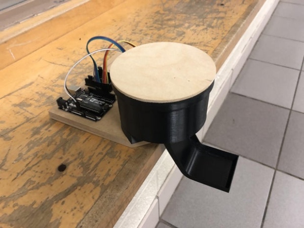
This is a simple touchless candy dispenser using an ultrasonic sensor for activation, a stepper motor to dispense candy, and an Arduino for controlling everything.
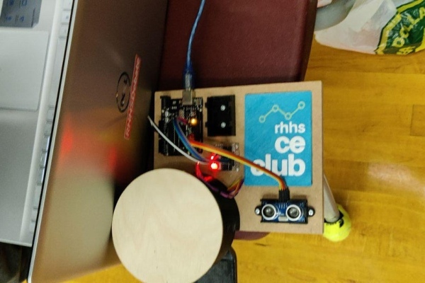
The candy dispenser can be powered using the USB port or using a 9v battery.
Inside the cylindrical container, there is a part with spokes that is turned by the stepper motor mounted underneath. Candy is placed between the spokes, and as the stepper motor turns, candy falls through a hole in the bottom of the cylindrical container onto a ramp where it is easy for someone to pick it up. There are 5 slots between the spokes for candies, so this can dispense up to 5 times before requiring a refill. Refilling is also made very easy with a screw-on lid that screws on or off with only a quarter turn.
This was designed in Fusion 360. The CAD file is below.
The software for this was done by Vivian Dai.
Supplies
Tools:
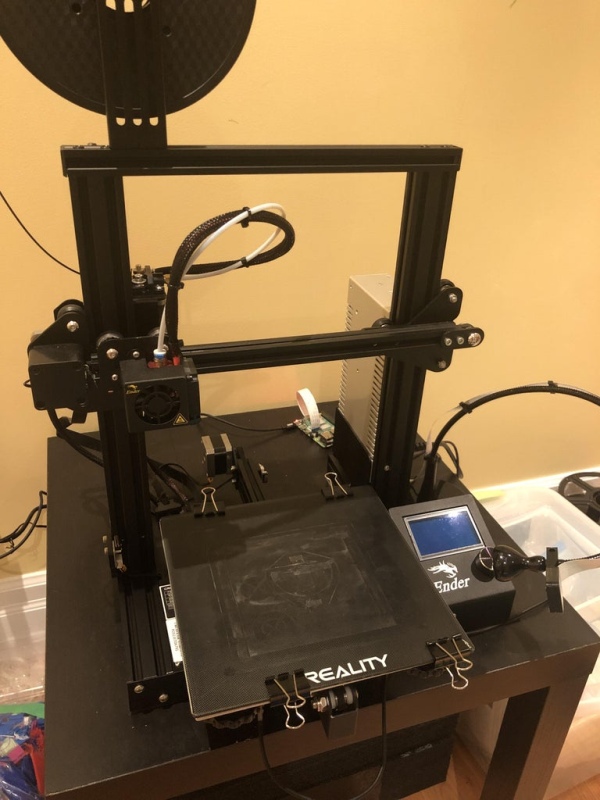
- a 3d printer (I used my Ender 3)
- a CNC mill (I used my homemade MPCNC: https://docs.v1engineering.com/mpcnc/intro/, alternatively the milled parts can also be 3d printed if you don’t have a mill)
- Sandpaper
- Glue (I mostly used superglue)
- A drill with some various sized drill bits is nice to have
Materials:
- 3d printing filament (I used PETG but PLA probably works better due to higher rigidity)
- A small piece of MDF (I used 3/4″ thick MDF, but the exact thickness doesn’t really matter)
- A small piece of plywood (used in the lid and for the spokes)
- Screws
- Really this doesn’t matter too much, as long as they work. I used a mix of M2.5×12 screws, some random self-tapping screws I found lying around, and some of those small screws that come with micro servos. The length of screws isn’t very important and holes can also be drilled out to fit M3 or other screws.
- WD-40 or other lubricant (optional, for lubricating the 3d printed threads of the lid)
Electronics:
- An Arduino Uno
- 28BYJ-48 stepper motor
- ULN2003 stepper motor driver
- HC-SR04 ultrasonic sensor
- 9v battery and connector with barrel jack for the Arduino (optional, can also use USB port for power)
Step 1: CNC Milling
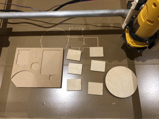
Mill out the base and lid cover from MDF or plywood. The material thickness for these doesn’t matter much, although I used plywood about 5.9mm thick and 3/4″ MDF.
The spokes of the rotating mechanism are also made of plywood, although these can be cut out without a mill using a scroll saw, bandsaw, or something else.
Don’t worry if you don’t have an end mill suitable for drilling the pilot holes, these can be done manually as I did.
You can also use to the Fusion 360 file above for milling.
Of course, all of these parts can also be 3d printed if you don’t want to or can’t use wood/MDF.
Step 2: 3d Printing
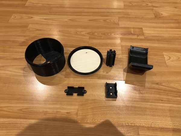
Next, all of the 3d printed parts need to be made. I printed them in black PETG but pretty much any material will work for this purpose.
In addition to the files below, you’ll also need a few things from Thingiverse:
- 9v battery holder: https://www.thingiverse.com/thing:336319
- Ultrasonic sensor holder: https://www.thingiverse.com/thing:936318
Step 3: Drilling & Countersinking Holes in the Base
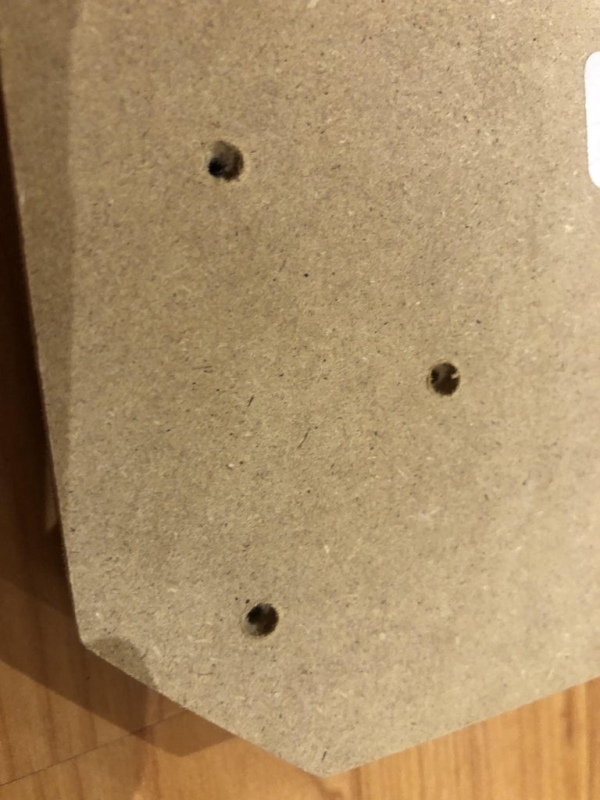
The stepper motor mount part has three holes that need to align with three holes in the base. These holes should also be countersunk from the bottom (you can use a large drill bit for this if you don’t have a proper coutnersinking bit). Later the screws to hold these parts together will come in from the bottom. Use an appropriate size of drill bit for the screws you will be using, I used M2.5×12 screws for these.
If you already made these holes on your CNC, all you need to do is countersink them from the bottom.
Step 4: Assembling the Spokes

The plywood spokes fit into the grooves in the 3d printed central hub part. If they don’t friction fit properly some glue can be used to hold them in place.
Step 5: Assembling the Lid
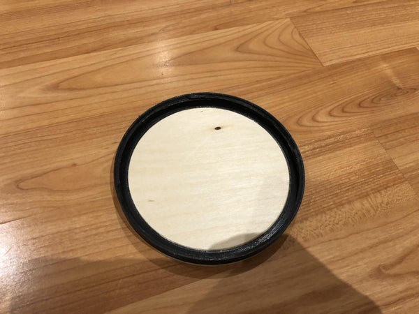
The 3d printed ring with the threads for the lid should fit into the carved portion of the plywood piece. These should be glued together to form the lid.
Step 6: Attaching the Ramp
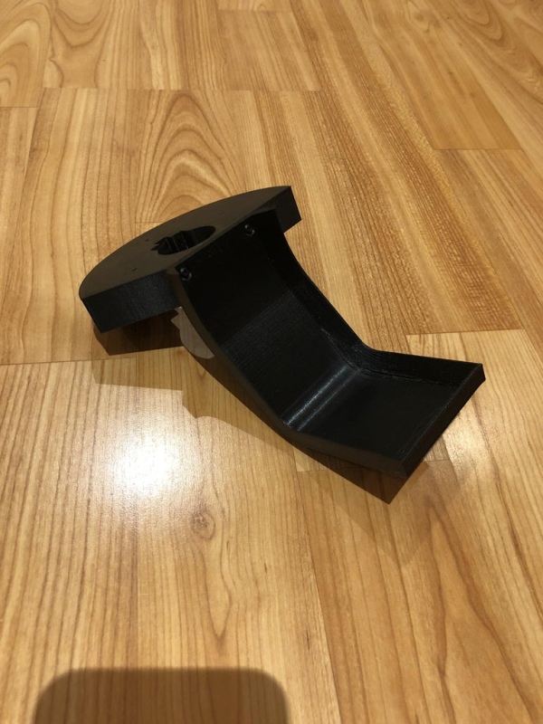
The ramp is attached to the stepper motor holder part using two screws. I used two M2.5×12 screws for this, but pretty much any small screws will work. Try to use screws that countersink properly so that the screw head doesn’t stick out too much.
Step 7: Assembling the Candy Compartment
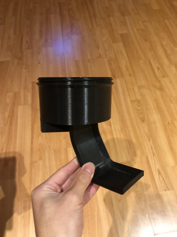
Now to assemble all the candy compartment parts.
The first step is to take your stepper motor and feed the wire through the hole in the stepper motor holder, and sliding the motor into place. It should be relatively secure. Once this is done, the main body of the candy compartment can be placed on top, and the top of the stepper motor should align with the outline indent on the bottom of the candy compartment body. Once this is aligned, there are three screw holes in the bottom of the candy compartment, three screws can be used to screw the candy compartment body to the stepper motor holder, which should clamp the stepper motor in place. I used three M2.5×12 screws for this.
Next, the entire rotating part with the spokes installed can be fit onto the shaft of the stepper motor.
Finally, the lid can be screwed on. If the lid does not move smoothly I would recommend using some WD-40 or other lubricant and screwing/unscrewing it a few times to get it moving nicer.
Step 8: Mounting Everything to the Base
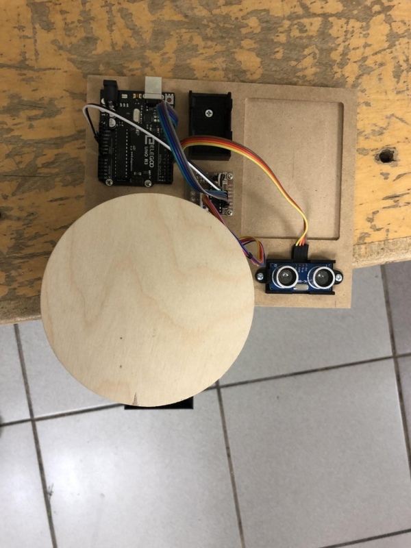
The first thing to mount to the base is the main candy compartment. Align it with the base and use three screws in the holes that have already been drilled out, screwing them in from the bottom of the base.
If they haven’t been drilled out already, the holes for mounting all of the electronics can be drilled by positioning the component on the base, marking out hole positions with a pencil, and drilling with an appropriately sized drill bit for the screws you will be using. I used servo screws for mounting the motor driver and Arduino, and some random self-tapping screws I found for the 9v battery holder and ultrasonic holder.
After drilling all pilot holes, all electronic components can be screwed onto the base.
Step 9: Wiring Electronics
Wiring for this is fairly straightforward. Connect pins as follows:
Ultrasonic sensor:
gnd  -- 4
echo -- 5
trig -- 6
vcc  -- 7

Stepper motor driver:
in1  -- 11
in2  -- 10
in3  -- 9
in4  -- 8
5-12V (+) -- 5V
5-12V (-) -- GND
Step 10: Code
The code for this was done by Vivian Dai and can be found on her Github here: https://github.com/vivian-dai/RandomDumpOfSmallStupidProjects/blob/main/UltrasonicCandyDispenser/UltrasonicCandyDispenser.ino
The code will turn the stepper motor when the ultrasonic sensor detects an object, dispensing the candy in the next compartment.
Source: A Simple Arduino Touchless Candy Dispenser