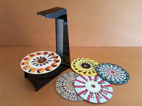
The Phenakistoscope is an early optical illusion device that uses static images to create the illusion of motion through the principle of persistence of vision. It is regarded as one of the first forms of moving media entertainment that paved the way for the motion picture industry.
We are not sure how big is the community currently interested in phenakistoscopes, however, from browsing through the internet, there seems to be quite a huge interest in this subject.
If you do not know how a phenakistoscope works, you may visit https://youtu.be/r4B3FHHt_k8 to see one in action.
It may be amazing to watch the mirror reflected images come to life by peeking through the slits or slots of phenakistoscopes, however, it can be quite tiresome when viewing for an extended period of time.
In this instructable, we are going to build a modern phenakistoscope. The phenakistoscope disc shall be mounted on a motor rotating at a speed that works with a strobing LED strip to make the images on the disc magically come to life when viewed with our naked eyes.
A traditional phenakistoscope is normally used by a person at a time. Our design allows a few people to view the animation at the same time which should be much more fun.
Our modern phenakistoscope can be controlled to rotate the disc in either clockwise or anti-clockwise direction, change the speed of rotation as well as vary the frequency of the strobe light. We will also be able to adjust the brightness of the strobe light for better viewing.
To build this project, basic electronics component soldering skill and some knowledge on using the Arduino are required.
You may like to view the following YouTube video to see what we are going to build for this project.
CAUTION:
For a small percentage of people with epilepsy, exposure to flashing lights at certain intensities or to certain visual patterns can trigger seizures.
This project requires strobing of the LED strip lights. If you experience discomfort looking at the images on the rotating disc or the light from the LED strip, you should stop looking at them immediately.
Step 1: Building the Electronic Circuit Board
For this project, we need a motor to spin at a consistent speed for the best visual effect.
We tested with cheap DC motors but they are not able to spin at a consistent speed over time. Motor speed slowly drifts lower after running the motor for a while and this is quite noticeable for this project as we have to regularly compensate by adjusting the strobe light frequency in order to stabilize the animation. We may be able to mitigate this using PID motor control but this will require motor feedback and more elaborate program codes.
We have some faulty CDROM drives lying around and the salvaged CDROM Brushless DC (BLDC) motors from these drives work great for this project. We were able to drive these BLDC motors at a much consistent speed without using any feedback mechanism. The CDROM motor disc holder also allows us to easily mount a CD/DVD disc with a phenakistoscope image pasted onto it.
We will not be showing how to salvage the BLDC motors from CD or DVD drives as this information is readily found online such as the following Instructable
https://www.instructables.com/Disassembling-a-CDDVD-reader-and-reusing-its-parts/
and YouTube videos such as the following which also show where to connect to the 3 phases of the BLDC motor.
The electronic circuit and program codes to drive the CDROM Brushless motor are adapted from the following two Instructables:
https://www.instructables.com/Run-A-CDROM-Brushles…
https://www.instructables.com/Arduino-CDROM-BLDC-M…
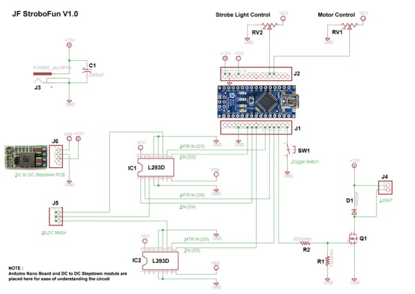
We will be using two L293D ICs for driving the CDROM BLDC motor and we will be using a DC to DC Step-down module to supply power to the motor.
We will be driving the BLDC motor in open-loop operation mode without the need for rotor position sensors since reliability is not critical here and also to simplify the electronic circuit.
In our design, we will need 2 potentiometers. One for strobe light frequency control and another for motor direction change as well as for motor speed change.
A toggle switch will be used for the brightness control of the strobe light. Light will be brighter with each switch toggle and return to default brightness level after 10 brightness incremental steps.
As with most of our projects, we will be using our favorite Arduino Nano board for this project due to its small form factor and ease of use.
A 12V 2A DC power supply adapter is required to power the entire project.
The schematic diagram for our project can be found above. If you have basic electronics knowledge, it should not be too difficult to put the electronic circuit together.
You may connect the electronic circuit on perfboard or breadboards. However, if you prefer something easier to work with, we have designed an electronics DIY kit for this project which is available at our Tindie store.
You may check out the YouTube video on how to assemble the electronics components onto the PCB board we have designed.
NOTE:
The following are to be observed during PCB assembly:
- Ensure the orientation of the IC chips (IC1 & IC2), capacitor (C1), diode (D1) and MOSFET (Q1) is correct.
- Ensure all components are soldered onto the TOP side of the PCB.
Step 2: Interface Circuit Board With Motor and LED Strip
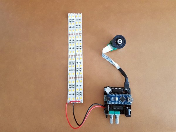
We will be using a DC to DC Step-down module to supply power to the two L293D ICs for driving the CDROM motor. At this stage, with the PCB module fully assembled but without the BLDC motor, LED strips and Arduino Nano micro-controller installed, we will power up our PCB module with 12VDC and adjust the knob on the DC to DC Step-down module until terminal VO+ is at around 3.5V.
PCB port J5 is to be connected to the 3 motor coil terminals of the CD/DVD drive BLDC motor. If you salvage the motor from CD/DVD drives, most probably it is mounted onto a PCB and attached with a cable consisting of more than 3 terminals. The CD drive BLDC motor we have comes with 11 terminals. We will need to figure out which 3 terminals are connected to the coils of the BLDC motor.
This can be determined by measuring the resistance between 2 terminals. There should be 3 terminals whereby any 2 of these 3 terminals have a resistance of just a few ohms.
The 3 motor coil terminals can be connected to any position of port J5. However, we prefer to connect them so that turning the potentiometer RV1 in clockwise direction will drive the motor in the clockwise direction and vice versa.
If our motor is rotating in the opposite direction, we can easily reverse the direction by exchanging the motor coil wires between J5 position 1 and 3. However, we can only verify that in Step 5 after the Arduino Nano is loaded with our program code.
See the image above on how the CDROM BLDC motor and 12V DC LED strip are to be connected to the assembled PCB module.
Step 3: Build the Phenakistoscope Platform Stand
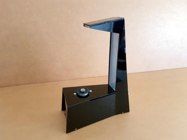
The image above shows the platform stand we have designed for our modern Phenakistoscope. We used 3mm thick acrylic sheets to build our stand.
We will not elaborate on how we design and build our platform stand here. You can put on your creative thinking cap and come up with your own platform stand design. You may build it using strong cardboards instead of acrylic sheets since they are easier to work with.
You may view the following YouTube video on how we put our Phenakistoscope platform stand
Step 4: Program the Arduino Board

We have adapted the codes for driving our CDROM BLDC motor from the following instructable.
https://www.instructables.com/Arduino-CDROM-BLDC-Motor-Driver-Enhanced-Performan/
The Arduino sketch for our project can be downloaded at the link below:
Click here to download JF Modern Phenakistoscope program.
Finally, upload the program to your Arduino Nano/compatible micro-controller board. We will not elaborate on how to upload the program into your micro-controller here as this information is readily available online.
Step 5: Final Modern Phenakistoscope Assembly and Adjustments
At this stage, the PCB module needs to be dismantled from our platform stand but with the LED strips and motor still connected so we can access to the DC to DC Step-down module adjustment knob to change output voltage VO+
With our Arduino Nano already loaded with our JF Modern Phenakistoscope program, we will now slowly increase the output voltage VO+ by adjusting the knob clockwise a little at a time until the motor with 2 CD/DVD discs mounted is able to start spinning consistently upon power-up.
CDROM BLDC motors are not designed to carry heavy load. So do not place heavy objects on them and attempt to increase the DC to DC Step-down module VO+ output voltage in order to spin them.
In Step 2, we mentioned that the 3 motor coil terminals can be connected to any position of port J5 but we prefer to connect them so that turning the potentiometer RV1 in clockwise direction will drive the motor in the clockwise direction and vice versa. We can verify this at this juncture.
If the motor rotational direction is not correct, this can easily be resolved by exchanging the motor coil wires between J5 positions 1 and 3.
Once adjustment is completed, we will now mount the PCB module back onto the platform stand and secure the base.
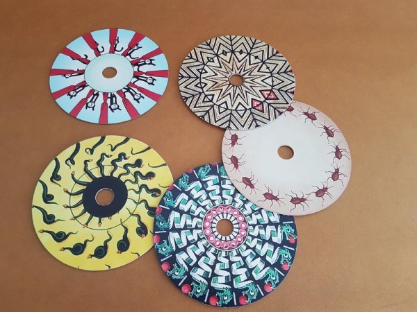
We searched online and selected some Phenakistoscope disc designs and resized them to fit onto standard size 120 millimeters (4.7 in) in diameter CD discs. They were then printed on 5R size matte photo paper and then cut and paste onto the CD/DVD disc. Centre holes are cut on most to fit onto the CD/DVD BLDC motor.
However, for some designs, we prefer not to cut the center hole as it may not do justice to the design. To mount these discs without center holes, we created a base disc by pasting a circular non-skid mat on it. This base disc shall then be mounted onto the CD/DVD BLDC motor first and those Phenakistoscope image discs without center holes are simply placed onto it. The non-skid mat prevents the upper disc from flying off when the motor is rotating.
There may be copyrights to the Phenakistoscope images we used for our testing. So we will not be providing them here for downloads.
Now for the final moment, cross your fingers and power up your Modern Phenakistoscope and be mesmerized watching the images on the Phenakistoscope discs come to life.
Source: A Modern Take on the Phenakistoscope
