
Summary of Representing audio through vibration with Arduino
This project converts audio into tactile vibration so users (including deaf people) can feel sound loudness by connecting an audio source (iPod, computer, TV) to an Arduino-driven array of pager motors. It uses simple electronics on a breadboard with resistors, capacitors, LEDs, and a 3.5mm stereo jack; wires are soldered to the jack and components are arranged per the provided circuit diagram and Arduino code.
Parts used in the Representing audio through vibration with Arduino:
- Arduino
- USB Cable
- Computer running Arduino software
- Breadboard
- LEDs
- Pager Motors
- Three 100K resistors
- Six 220uF capacitors
- 1K potentiometer
- 3-Conductor Stereo 1/8 inch (3.5mm) Phone Jack
- Wires
- Solder
- Circuit diagram
- Arduino code
This project functions to display sound using vibration. You plug your iPod, computer, or TV into it and get tactile feedback representing the loudness of the audio. It can help deaf people to experience sound.
Stuff you need:
Arduino
USB Cable
Computer running Arduino software (www.arduino.cc/download/)
Breadboard
LEDs
Pager Motors
Three 100K resistors
Six 220uF resistors
1K potentiometer
3-Conductor Stereo 1/8″ (3.5mm) Phone Jack
Wires
Solder
Circuit diagram
Arduino code
Step 1: Cut wires and strip those entire wires ends 1/2 cm
Use wire stripper to cut and strip.
Cut 8 1” pieces of wires for LEDs, Phone Jack and breadboard.
Cut 8 3″ pieces of wires for connecting between Arduino pins and breadboard
Cut 6 5″ pieces of wires for pager motors
Strip those entire wires’ ends ½ cm
Step 2: Solder the wires to 3-conductor stereo 1/8 phone jack
Warning: Soldering Iron is very hot It’s little hard to solder between wires and pager motors’ wires because pager motors’ wires are very tiny.
Use six 5″ wires for this. You can twist black and red wire together but make sure that both wire metals doesn’t touch each other. Otherwise it will be short circuit break and you may damage pager motors.
black wire to blue wire of pager motor for ground
red wire to red wire of pager motor for power
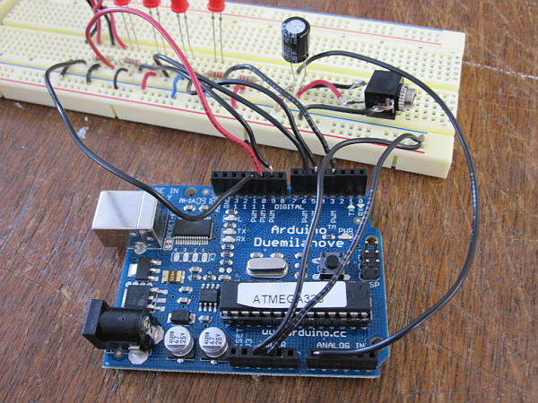
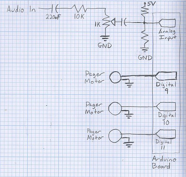
Step 3: Set up the breadboard and follow circuit diagram
Follow a circuit diagram and set up the breadboard how circuit diagram tells you using small pieces of wires. Insert resistors, LEDs, pager motors, capacitor and phone jack.
For more detail: Representing audio through vibration with Arduino
- What does this project do?
It converts audio input into tactile vibration representing loudness so users can feel sound. - What audio sources can be used with this project?
You can plug in an iPod, computer, or TV. - What microcontroller is required?
An Arduino is required. - How are the pager motors connected to the audio jack?
You solder wires from the 3-conductor phone jack to the pager motors, matching ground and power as described. - What resistors and capacitors are needed?
The project uses three 100K resistors and six 220uF capacitors. - Is soldering necessary?
Yes, soldering is used to attach wires to the 3.5mm phone jack and to connect small motor wires. - What should be used to follow the circuit connections?
You should set up components on a breadboard following the provided circuit diagram. - How many wires should be cut and prepared for the project?
Cut eight 1-inch wires, eight 3-inch wires, and six 5-inch wires as specified, then strip 1/2 cm from each end.