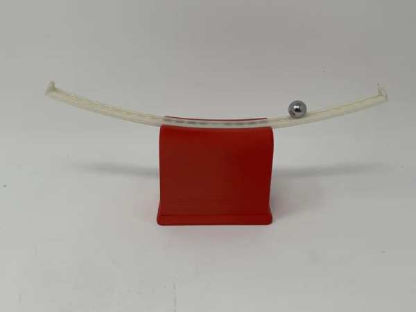
“Marblevator, Pertual?, Cradle” like “Marblevator, Perpetual?, Version 2” and “Marblevator, Perpetual?” is not perpetual at all as it is simply another illusion. And like its predecessors it is a very quiet illusion with the only noise being that of the marble as it rolls back and forth in the cradle.
I’ve incorporated an Arduino Nano 33 IoT in this model. The Nano software controls the illusion using two interrupt service routines activated by two infrared transceivers. When the ball bearing passes over an infrared transceiver, an interrupt is generated via the Nano input pin associated with the infrared transceiver, causing the interrupt service routine associated with the pin to be called. Each interrupt service routine utilizes the interrupt history of both interrupt service routines in order to detect downhill ball bearing motion. When downhill motion is detected, the software pulses an electromagnetic coil in order to accelerate the ball bearing up the other side of the track (as the model uses infrared transceivers to sense the ball bearing, it cannot be operated where an external source of infrared is present as that will flood the infrared transceivers thus render the model inoperative).
I’ve also included software that monitors the battery voltage via a resistor divider and analog input pin to put the Nano to sleep when the LiPo battery voltage drops below a specified cutoff level (9.6vdc).
As usual, I probably forgot a file or two or who knows what else, so if you have any questions, please do not hesitate to ask as I do make plenty of mistakes.
Designed using Autodesk Fusion 360, sliced using Ultimaker Cura 4.12.1, and 3D printed in PLA on Ultimaker S5s.
One final note, I receive no compensation in any form for the design, parts and/or materials used in this model.
Supplies
- Soldering iron and solder.
- One roll each of red, black, green and blue 28AWG stranded wire.
- Micromesh polishing sheets (1200, 1500, 2400, 3200).
- Sandpaper (120, 220, 400 and 600 grit).
- Thick cyanoacrylate glue.
- Double sided tape.
- Velcro.
- Heat shrink tubing.
Step 1: Parts.
I acquired the following parts:
- One Arduino Nano 33 IoT [ABX00027]
- One 11.1vdc 300mAh 3S 30C battery LiPo battery.
- One JST mating connector for the battery.
- One Gikfun EK1909 “magnetic levitation coil”.
- Two TCRT5000 infrared transceivers.
- One FQP30N06L MOSFET.
- One 1N4007 diode.
- One 10kΩ resistor.
- One 2.7kΩ resistor.
- Two 1KΩ resistors.
- One M3 by 8mm cap screw.
- One 11MM diameter ball bearing.
- One M3 by 8mm cap screw.
I 3D printed the following parts at .1mm layer height, 20% infill:
- One “Base.stl” with PLA support.
- Two “Bolt, Mount, Coil.stl”.
- One “Bottom.stl”.
- One “Mount, Coil.stl”.
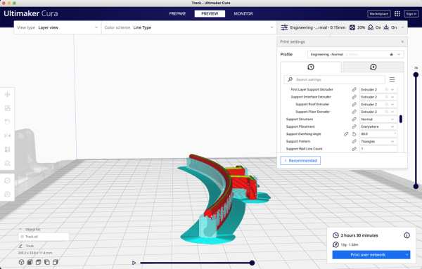
- One “Track.stl” with breakaway or PVA support (requires a dual extrusion 3D printer, see Cura image above).
This is a precision print and assembly model using at times very small parts and in very tight spaces. Prior to assembly, test fit and trim, file, sand, etc. all parts as necessary for smooth movement of moving surfaces, and tight fit for non moving surfaces. Depending on you printer, your printer settings and the colors you chose, more or less trimming, filing and/or sanding may be required. Carefully file all edges that contacted the build plate to make absolutely certain that all build plate “ooze” is removed and that all edges are smooth. I used small jewelers files and plenty of patience to perform this step. After 3D printing “Base.stl” and “Track.stl” I carefully removed the support material using a flat jewelers screwdriver and needle nose pliers.
The model also uses threaded assembly thus an M8 by 1.25 tap and die will assist with thread cleaning if necessary.
Step 2: Board and Coil Mount Assembly.
Referring to the included schematic diagram of the electronic design for this model, I assembled the board and coil mount as follows:
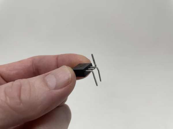
- Bent the MOSFET gate and source leads downward, then bent the drain lead up upward.
- Insulated the back side of the MOSFET heatsink tab with electrical tape.
- Inserted the 2.7kΩ resistor between pin A7 and GND of the Nano.
- Inserted the 10kΩ resistor on top of the 2.7kΩ resistor between pin A7 and Vin pins of the Nano.
- Soldered the previous two inserted resistors to the Nano and trimmed the leads.
- Attached the coil to “Mount, Board and Coil.stl” using the cap screw.
- Inserted the MOSFET from the underside into the Nano, gate pin to D3 and source pin to GND, drain pin upward.
- Snapped the Nano into the mount assembly.
- Positioned the MOSFET 3mm above the underside surface of the Nano, soldered the MOSFET gate and ground leads to the Nano, then trimmed the gate lead, leaving the source lead as is for soldering later.
- Wrapped one uninsulated coil wire tip around the MOSFET drain pin then soldered it.
- Wrapped the anode lead of the diode around the MOSFET drain pin then soldered it.
- Wrapped the remaining uninsulated coil wire tip around the cathode lead of the diode then soldered it.
- Slipped heat shrink tubing over the JST mating connector black wire, soldered the black wire to the MOSFET source lead, slipped the heat shrink over the soldered joint and applied just enough heat for the heat shrink to insulate the joint.
- Soldered the JST mating connector red wire to the cathode lead of the diode.
- Glued the red wire insulation of the JST mating connector to the mount for strain relief.
- Soldered a 60mm length of wire between the diode cathode to the VIN pin of the Nano.
- Carefully bent the MOSFET insulated source lead flat to the board.
- Glued the red and black wire insulation of the JST mating connector to the mount for strain relief.
Step 3: Infrared Transceivers Assembly.
Again referring to the included schematic diagram of the electronic design for this model, I assembled the infrared sensors as follows:
- Bent the first TCRT5000 anode lead over to the first TCRT5000 emitter lead, soldered the two leads together, then trimmed all the leads.
- Soldered a 1KΩ resistor to the first TCRT5000 anode lead.
- Soldered an 80mm length of red wire to the free end of the 1KΩ resistor then insulated the resistor solder joints with heat shrink tubing.
- Soldered an 80mm length of black wire to the first TCRT5000 emitter lead.
- Soldered an 80mm length of green wire to the first TCRT5000 collector lead then insulated the solder joint with heat shrink tubing.
- Bent the second TCRT5000 anode lead to the second TCRT5000 cathode lead, soldered the two leads together, then trimmed all the leads.
- Soldered a 1KΩ resistor to the second TCRT5000 anode lead.
- Soldered an 80mm length of blue wire to the second TCRT5000 collector lead then insulated the solder joint with heat shrink tubing.
- Positioned the first TCRT5000 assembly near the mount assembly, inserted its wires the into the first TCRT5000 hole in the mount assembly then routed them up through the second TCRT5000 hole in the mount assembly.
- Soldered an 80mm length of black wire and the black wire from the first TCRT5000 assembly to the second TCRT5000 emitter lead.
- Soldered an 80mm length of red wire and the red wire from the TCRT5000 assembly together, slipped a 20mm length of heat shrink tubing over the wires, soldered these wires to the second TCRT5000 resistor free end, slid the heat shrink tubing over the solder joint and applied heat to shrink it.
- Soldered the green wire from the first TCRT5000 to the Nano pin D10.
- Soldered the blue wire from the second TCRT5000 to the Nano pin D9.
- Soldered the black wire from the second TCRT5000 to the Nano GND pin.
- Soldered the red wire from the second TCRT5000 to the Nano 3.3V pin.
- Sanded the ball bearing rails on “Track.stl” starting with 120 grit sandpaper, followed with 220, 400 and 600 grit, then finely polished the rails using Micromesh 1500, 1800, 2400 and 3200 sheets.
- Carefully slid each TCRT5000 into the transceiver sockets in the track.
- Attached the track to the mount assembly using two “Bolt, Mount, Board and Coil.stl”.
Step 4: Software.
I have included the Arduino file “MarblevatorCradle.ino” containing the software that will be downloaded into the Nano. The software is divided into four sections; setup(), loop(), InterruptServiceInfraredTransceiver1() and InterruptServiceInfraredTransceiver2().
The setup() function contains the initialization code. After disabling interrupts, the code assigns the pin used to drive the mosfet as a digital output and clears the output. Next the two infrared transceiver input pins are assigned and the respective interrupts attached. Finally the software sets the built in LED pin as an output, then enables interrupts.
The loop() function contains code required to monitor battery voltage. The LiPo battery I used in this model does not have low voltage cutoff protection, so I’ve tasked the Nano loop() function with this responsibility. After declaring, initializing and calculating the various battery voltage parameters, a ten second delay is encountered. After the delay, the battery voltage a/d count is acquired and compared with the calculated cutoff a/d count. If the battery voltage falls below the cutoff, the Nano is put to sleep.
Finally are the two interrupt service routines, InterruptServiceInfraredTransceiver1() and InterruptServiceInfraredTransceiver2(), each one associated with one of the infrared transceivers. When the ball bearing rolls over an infrared transceiver, the infrared transceiver collector output will go low causing that infrared transceiver’s interrupt service routine to be called. After a delay, the interrupt service routine waits for the rising edge of the interrupt pin then determines whether or not to pulse the coil. At this point the global variable “bLastInfraredTransceiverSensorInterrupt” will contain one of three values; 0, 1 or 2. If 0, no interrupts have previously occurred indicating the model has just powered on thus the coil will be pulsed. If 1 and the current interrupt service routine is 1, or if 2 and the current interrupt service routine is 2, then the interrupt service routine was the previous interrupt service routine when the bearing was rolling uphill. A second interrupt in a row on the same interrupt service routine indicates the ball bearing is rolling downhill thus the coil will be pulsed. Whether the coil is pulsed or not, the software records the interrupt service sensor number in “bLastInfraredTransceiverSensorInterrupt” in preparation for the next interrupt.
Step 5: Ball Bearing Travel Adjustment.
The software includes the constant “COIL_ON_MICROSECONDS” that I set to 1600 microseconds (1.6 milliseconds). Depending on how well the track ball bearing rails were sanded and polished, this value may need to be decreased if the ball bearing travels too far (e.g. collides with the track end caps), or increased if the ball bearing does not travel far enough. To adjust the value of COIL_ON_MICROSECONDS, I perform the following steps:
Place the track and mount assembly in a small vice and check for level and if not level, I level it.
Connect the Nano to a USB port on my computer, download the software to the Nano, then disconnect the USB cable.
Connect the battery to the assembly JST connector.
Place the ball bearing at one end of the track and release it.
Monitor the ball bearing movement.
If travel adjustment is necessary, I unplug the battery, connect the USB cable to the Nano, change the value of COIL_ON_MICROSECONDS by 100 to 150, download the change to the Nano, disconnect the USB cable, reconnect the battery, then repeat as necessary.
If the value of COIL_ON_MICROSECONDS becomes too large (exceeds 3000 microseconds of 3.0 milliseconds), I polish the track again as the coil may become warm enough to distort the mount assembly and/or track. I measured an average coil temperature rise over ambient room temperature (72 degrees) of the prototype model at about 2 degrees F (thus the coil temperature was 74 degrees F.).
With a coil pulse width of 1.6ms, the ball bearing in the prototype model rolls just short of end cap to end cap, using a maximum current draw of 112mAh (during coil pulse), a minimum current draw of 10mAh (prior to placing the ball bearing on the track), and an average current draw of 25mAh (after 30 minutes of operation).
Step 6: Final Assembly.
For final assembly, after ball bearing travel adjustment. I performed the following steps:
- Unplugged the battery.
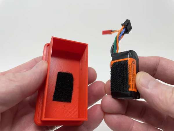
- Attached the battery to “Base.stl” using Velcro.
- Removed the bolts holding the track to the mount assembly.
- Carefully removed the TCRT5000 assemblies from the track sockets.
- Placed the mount assembly into “Case.stl” such that the TCRT5000 assemblies exited the track slot at the top of the case.
- Carefully inserted the TCRT5000 assemblies fully into the track sockets.
- Secured the track to the mount assembly and case with the two bolts.
- Plugged in the battery.
- Pressed the base assembly into the case assembly.
- Released the ball bearing from one end of the track.
And that is how I 3D printed, soldered, adjusted and assembled “Marblevator, Perpetual?, Cradle.”
Source: Marblevator, Perpetual?, Cradle.