Summary of The scope…from Hell Using Arduino
This article reviews a low-cost, two-channel bench oscilloscope that falls short of its advertised four-channel, 5GSa/s specifications. While the analog performance slightly exceeds the 100MHz bandwidth claim and features like variable digital filters and PC software are praised, the device suffers from numerous firmware bugs. The author notes significant issues with math functions and FFT stability but highlights the lack of manufacturer support after five months of negotiation for fixes.
Parts used in the Oscilloscope Review:
- Bench scope
- ECL signal source
- BNC-T connector
- 50 ohm terminator
- PC software
- USB connection
What I asked for was a general purpose 5GSa/s 1GHz four-channel bench scope. What I got was a 1GSa/s 100MHz two-channel. Still, it is somewhat usable, and less expensive than a fancy temperature-controlled soldering station. But it has bugs – many bugs.
I have been negotiating with the manufacturer to get a firmware update to fix these bugs. After five months, no results. This scope has been designed to accept firmware updates. Good planning. It needs them – desperately. (“Ship now and fix the bugs later. We have a schedule to keep!”)
Before listing all the functional problems, let me elaborate on what I actually like about this scope. The advertised bandwidth is 100MHz, but when feeding in a 300ps edge (ECL directly into the scope with a BNC-T 50 ohm terminator), the measured scope risetime indicates the bandwidth is more like 140MHz. Hurrah for the analog designers!
The variable frequency digital filter function (highpass, bandpass, band-reject, and lowpass) works nicely on the display.
Another extremely nice feature is the PC software that allows screen captures for reports and record keeping. It usually works, unless the scope goes to sleep (more on this later), and with a USB connection, capturing a screen image on your PC is a piece of cake. Beats the heck out of sneakernet.
From here it goes downhill, rapidly. Those who wrote the operating firmware seem to have never used a scope. Those who wrote the user manual should have had it proofread and edited by someone competent in technical writing. There are many good features. It would be nice if they all worked properly, and so far I’ve barely scratched the surface.
Bug 1a
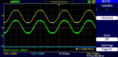
When using the math function, turning off the source channel(s) also turns off the math function. This should not happen according to the manual. There are many times one wants to see only the math trace.
Workaround: Leave the source channel(s) on and turn down the display intensity. This dims both channels, but leaves the math function visible since it has no intensity adjustment. (A bug dressed up in a tux becomes a feature.)
Bug 1b
Turning the FFT function off, then back on, changes the vertical position of the FFT display by 30dB. This really should remain where set by the user.
For more detail: The scope…from Hell!
- What was the actual specification received instead of the requested general purpose 5GSa/s 1GHz four-channel bench scope?
The user received a 1GSa/s 100MHz two-channel scope. - How did the measured risetime indicate the bandwidth compared to the advertised 100MHz?
Feeding a 300ps edge directly into the scope indicated the bandwidth is more like 140MHz. - Does the variable frequency digital filter function work on the display?
Yes, the highpass, bandpass, band-reject, and lowpass functions work nicely. - What workaround is suggested when the math function turns off along with the source channels?
Leave the source channels on and turn down the display intensity to keep the math trace visible. - Does turning the FFT function off and back on preserve the vertical position setting?
No, turning it off then on changes the vertical position by 30dB. - How long has the user been negotiating with the manufacturer for a firmware update?
The user has been negotiating for five months without results.