Summary of IoT Set-up to Operate/control 220-240 Volt AC Bulb/Device; NodeMCU Amica + 5V Relay + MQTT + Arduino IDE + Web Browser (HTML + JavaScript/jQuery)
Summary (under 100 words): An IoT setup using a NodeMCU Amica (ESP8266), a 5V relay, MQTT broker, Arduino IDE, and a web browser (HTML/JavaScript/jQuery) to remotely switch a 220–240V AC bulb or other appliance. The NodeMCU runs an Arduino sketch to connect to Wi‑Fi and subscribe to an MQTT topic; the browser publishes commands to the same topic. Relay contacts switch the AC live to the load. Warning: project involves hazardous mains voltages—unplug circuits and exercise caution.
Parts used in the IoT Set-up to Operate/control 220-240 Volt AC Bulb/Device:
- NodeMCU Amica (ESP8266 development board)
- 5V Relay module
- Jumper wires
- Breadboard
- 240V light bulb with lamp holder
- Electrical wires for 240V AC connections (live and neutral)
- USB cable to upload sketch to NodeMCU
- Computer with Arduino IDE
- Web browser (for HTML/JavaScript/jQuery client)
- MQTT broker (example used: iot.eclipse.org)
What are we messing with?
IoT (Internet of things) set-up to operate/control 220-240 Volt AC Bulb/Device
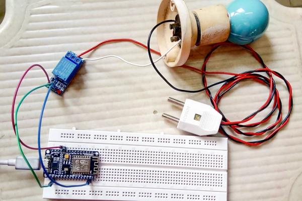
NodeMCU Amica + 5V Relay + MQTT + Arduino IDE + Web Browser (HTML + JavaScript/jQuery)
WARNING!! – THIS PROJECT INVOLVES WORKING WITH HIGH VOLTAGES THAT CAN CAUSE SERIOUS INJURY, DEATH, AND/OR SET YOUR HOUSE ON FIRE. PLEASE PROCEED WITH CAUTION, AND ALWAYS MAKE SURE CIRCUITS ARE UN-PLUGGED BEFORE WORKING ON THEM
Step 1: Prerequisites
Make sure to follow the instructions mentioned in the below link to proceed further.
https://www.instructables.com/id/Quick-Start-Guide…
Hardware:
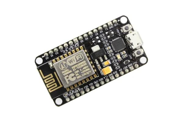
NodeMCU Amica
- Executes Arduino program(sketch)
- Has built-in ESP8266(WIFI module) which is the main reason to prefer NodeMCU over Arduino UNO board
5V Relay
- To switch any 240V device(bulb in our case) ON/OFF
Miscellaneous
- Jumper wires to connect the circuit
- Breadboard
- 240V light bulb with lamp holder
- Electrical wires to connect bulb & relay to 240V AC power supply
- USB wire to upload program to NodeMCU board from computer
Software:
MQTT (MQ Telemetry Transport)
- Medium of communication between NodeMCU development board and client(web/mobile) application – publish/subscribe pattern
- You may use MQTTLens chrome plugin to test out the connection to broker and try subscribing & publishing (not necessary needed)
Arduino IDE
- To develop a program which will subscribe to MQTT broker and fetch the latest message available and accordingly switch the 5V Relay
Web Browser
- Takes the user input command and publish to MQTT broker
Step 2: Wiring Diagram – Fritzing
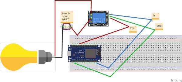
Although this fritzing project gives an insight to the required wiring setup, Below is a theoretical brief of the same:
NodeMCU 3V3 >>Relay VCC [red jumper wire]
NodeMCU D0 >>Relay IN [blue jumper wire]
NodeMCU GND >>Relay GND [green jumper wire]
Relay NO (Normally Open) >>Bulb +ve
Relay COM (common terminal) >>240V AC Live
Bulb -ve >>240V AC power Neutral
Step 3: Software Setup
HTML script:
When you open this html in browser
- Script will connect to the MQTT broker(iot.eclipse.org) and subscribes to a topic(/lamp/status/)
- Once you see connection is successful, click on the switch button which will accordingly publish the message to the topic
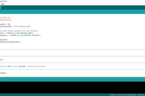
Arduino program(sketch):
This is the program should be uploaded to NodeMCU board, it will do the following work
- Connects to our WIFI(to specified SSID & password)
- Then connects to the MQTT public broker(iot.eclipse.org) and subscribe to the topic(/lamp/status/) same as HTML script
- When HTML does a publish to the topic in MQTT broker, callback is executed which will digitalWrite HIGH/LOW to D0 GPIO pin in NodeMCU board which in turn triggers 5V Relay ON/OFF
Step 4: Wrap Up
If you will just replace the bulb connections to any other electrical device like fan, computer, fridge etc., you should see it working for all of them.
But make sure you got the bulb working in the first place.
Thanks for reading.!
NOTE: I was not able to find any one specific article that is doing all the stuff that is being discussed here, But I have followed/referred to many different articles (from wiring to source code) to finally get to this set up, unfortunately I have lost track of most of them. If you have found any posts which have similar content kindly let me know. I am happy to credit them here.
P.S. To view images in detail with more clarity, please click on image which will open a popup of the same, and then click again which redirects to another page with a list of different image sizes where you can download better quality version of the image.
- What does the NodeMCU Amica do in this project?
The NodeMCU runs an Arduino sketch, connects to WiFi and the MQTT broker, subscribes to the topic, and toggles D0 to switch the 5V relay based on received messages. - How does the web browser control the bulb?
The HTML/JavaScript client connects to the MQTT broker and publishes messages to the /lamp/status/ topic when the switch button is clicked. - Which MQTT broker is used in the example?
The example uses the public broker iot.eclipse.org. - Which GPIO pin on NodeMCU is used to drive the relay?
D0 is used to digitalWrite HIGH/LOW to trigger the 5V relay. - How is the relay wired to the bulb and mains?
The relay NO goes to bulb positive, relay COM goes to 240V AC Live, and bulb negative goes to 240V AC Neutral. - Can this setup control devices other than a bulb?
Yes, the article states you can replace the bulb with other electrical devices like a fan, computer, or fridge. - What software is required to program the NodeMCU?
The Arduino IDE is used to develop and upload the sketch to the NodeMCU. - Is there a warning about safety in the project?
Yes, the project warns that working with high voltages can cause serious injury, death, or fire and advises caution and unplugging circuits before working on them.