
Summary of Mr.Skelleton
This article details a DIY Halloween project creating an interactive "Mr. Skeleton" basket that detects when hands reach for candy. Using an Arduino MEGA 2560, ultrasonic sensor, servo motor, and LEDs, the skull lights up, moves its head, and plays music to scare trick-or-treaters. The guide covers assembly steps including drilling holes, soldering electronics, and 3D printing supports to integrate the components into a plastic basket and skull.
Parts used in the Mr. Skeleton Halloween Basket:
- Plastic skull
- Halloween basket
- Plastic or carton recipient (for electronics)
- Candy
- Black fabric
- Red LEDs x2
- Resistor 220 Ohm x2
- MEGA 2560 Controller board
- Servo Motor
- Ultrasonic sensor
- Passive Buzzer
- 9V1A adapter
- Breadboard
- Breadboard Jumper wire x5
- Female-to-Male Dupont wire x10
- Glue gun
- Driller
- 3d printed support (optional)
- Electric iron solder (optional)
- Fake spiderwebs and spiders (optional)
- Skeleton hands (optional)
Are you prepared to experience the spookiest night of the year?
Grab some candy from this basket if you’re brave enough, but be careful: Mr. Skeleton doesn’t like sharing too much. Happy Halloween!
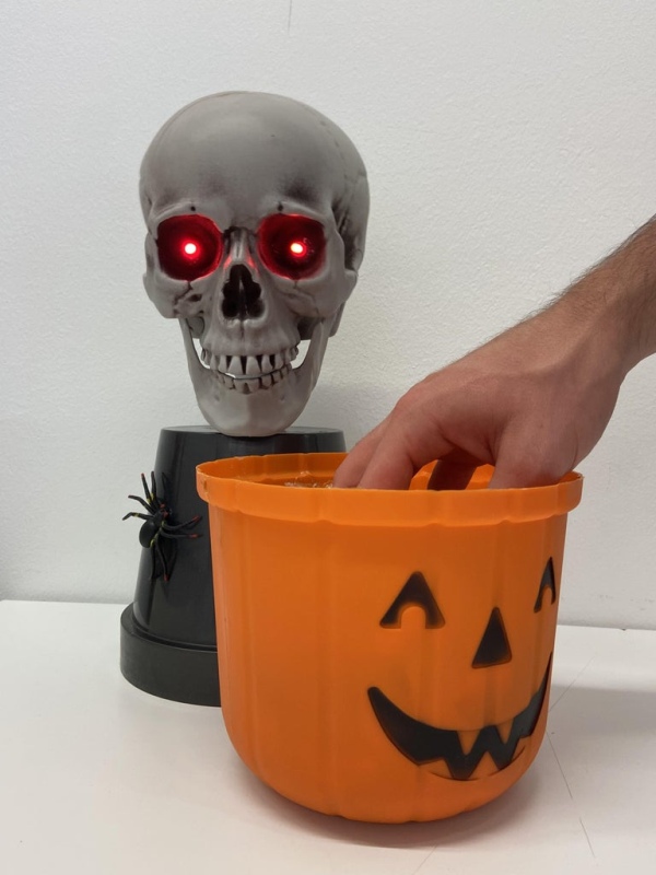
Halloween basket with built-in distance detector; when trying to reach for candy inside, the skull will light up its eyes and move its head from side to side while creepy music plays.
Supplies
To recreate this prototype, you will need some products and electronics:
- Plastic skull
- Halloween basket
- Plastic or carton recipient (for the electronics)
- Candy
- black fabric
- Red LEDs x2
- Resistor 220 Ohm x2
- MEGA 2560 Controller board
- Servo Motor
- Ultrasonic sensor
- Passive Buzzer
- 9V1A adapter
- Breadboard
- Breadboard Jumper wire x5
- Female-to-Male Dupont wire x10zs
- Glue gun
- Driller
- 3d printed support (optional)
- Electric iron solder (optional)
- fake spiderwebs and spiders (optional)
- skeleton hands (optional)
Step 1: Schematic
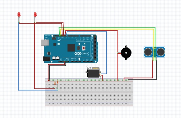
A schematic model of all the electrical connections made with Fritzing.
Step 2: Flow Diagram & Code
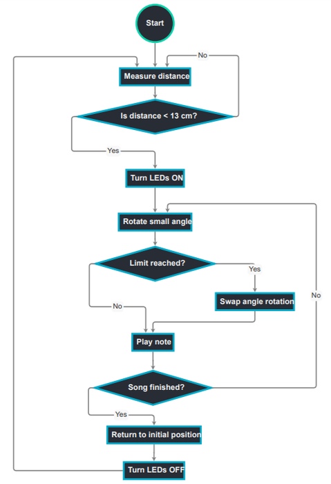
Flow diagram explaining how the code works, plus the actual code we will be using.
Step 3: Guide
Once we have all the components of the project and all are working correctly, we will have to get down to work with the construction of it.
Step 4: Halloween Basket
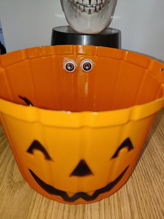
The first thing to do is to drill two holes in the upper part of the wall of the Halloween basket where the distance sensor will be inserted and fixed using hot silicone. It is very important to drill these two holes at a position where it can detect the distance reduction when a hand tries to reach for the candy. Determine the diameter of your basket and then decide which distance would activate the skull.
Step 5: Skull
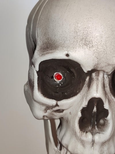
After this, two small holes should be made in the eye sockets of the skull where the LEDs will be inserted and fixed using hot silicone. A third hole must be drilled in the back of the skull to pass the cables of the LEDs and make them reach the interior of the bucket. Finally, the small plastic piece that comes with the servo motor must be screwed directly to the skull. The approximate center of mass of the skull must be taken into account when screwing the part, since, if it is off-center, the lateral movements of the skull could destabilize the entire structure.
Step 6: Bucket
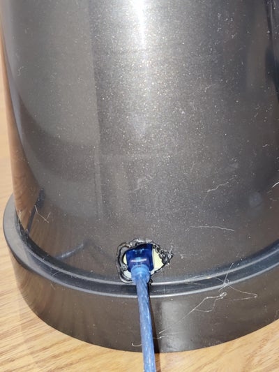
The bucket must be drilled in the upper central part to pass through the cables of the LEDs and the servo motor, in the front part to pass the cables of the distance sensor and in the back to be able to plug in the Arduino while it is inside of the bucket.
To join the skull and the bucket, a small support must be printed in 3D in which the servo will be inserted as well as through which the cables of the LEDs and the servo itself will be inserted into the bucket. Finally, the small piece screwed to the skull will be fixed by superglue to the servomotor. It is important to let this bond dry for several hours. With all the cables protruding from the skull inside the basket, the 3D support will be joined to it utilizing hot silicone and, finally, the servomotor will be inserted inside said support.
With all the cables correctly inserted inside the basket, we will proceed to connect everything and finally, hide all the electronics inside of it.
Step 7: Get Creative
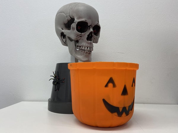
The only thing remaining is to decorate the project in any way you can imagine and, finally, scare some kids!
Step 8: Happy Halloween
There you have it, the spook machine is ready! This will make giving candy a lot more scary or funnier, depending on which side are you on. Prepare for Halloween and take care, hope you enjoyed the tutorial!
This project was possible thanks to the UATEA subject at Elisava University of Design and Engineering, which is about learning the basic concepts of programming and applying them to our products. The exercise helped us create a functionality using some electronics and the knowledge acquired, and also made us realize how to adapt and use the programming tools to make interactive experiences.
Source: Mr.Skelleton
- How does the Halloween basket detect hands?
The distance sensor is inserted and fixed using hot silicone to detect distance reduction when a hand tries to reach for the candy. - What happens when someone reaches for the candy?
The skull lights up its eyes, moves its head from side to side, and creepy music plays. - Which controller board is required for this project?
A MEGA 2560 Controller board is needed to run the code and manage the electronics. - How are the LEDs installed in the skull?
Two small holes are made in the eye sockets where LEDs are inserted and fixed using hot silicone. - Why must the center of mass be considered for the skull?
Considering the approximate center of mass prevents lateral movements from destabilizing the entire structure if the part is off-center. - Where should the holes be drilled in the bucket?
Holes must be drilled in the upper central part for cables, the front part for the distance sensor, and the back part to plug in the Arduino. - What optional material can be used for the servo support?
A 3d printed support is optional and can be used to insert the servo and pass cables into the bucket. - How is the skull attached to the servomotor?
The small piece screwed to the skull is fixed by superglue to the servomotor after letting the bond dry for several hours.
