
Summary of 3D Printed Holo Clock With Arduino
This article details the construction of a 3D-printed clock driven by an Arduino Uno and a stepper motor. Designed in OnShape, the project involves printing components in black and white PLA+, cutting and sanding brass tubes for shafts, assembling a multi-layer frame, installing gears, and wiring the electronics. The clock operates precisely via USB power once programmed.
Parts used in the 3D Printed Holo Clock:
- Arduino Uno
- 24BJY-48 stepper motor
- ULN2003 stepper motor driver
- 6 male to female jumper wires
- 3D printer
- Black and white PLA+ filament
- 2 M4 nuts
- 2 M4 screws 6mm long
- 4 M3 screws 10mm long
- 8 M3 washers
- Masking tape
- Super glue
- M4 and M3 allen wrenches
- Brass tube (3.18mm x .335mm)
- Vise and Dremel tool
Hello everyone! This is my first instructable.
This project is a 3D printed clock powered by a stepper motor and is controlled by an Arduino Uno. It was designed in OnShape over the course of a month. It keeps time very precisely and only needs to be plugged into a USB port once programmed.
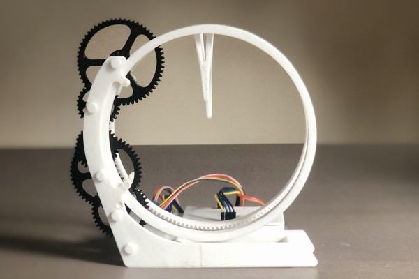
Credit to ekaggrat for the design idea.
There may be missing files or errors. If you spot any, let me know.
Supplies
Arduino Uno
24BJY-48 stepper motor
ULN2003 stepper motor driver
6 male to female jumper wires
A 3D printer
2 different colors of filament (I used black and white PLA+)
2 M4 nuts
2 M4 screws 6mm long
4 M3 screws 10mm long
8 M3 washers
Masking tape
Super glue
M4 and M3 allen wrenches
3.18mm x .335mm brass tube (see below)
Link for the brass tube: https://www.amazon.com/PRECISION-METALS-8127-RND-Tube/dp/B000BQOPWM/ref=sr_1_4?dchild=1&keywords=precision+metals+1%2F8+x+.014+brass+tube&qid=1626543332&sr=8-4
Note: I only used such a strange tube because it was all I had on hand.
Step 1: Print the Parts
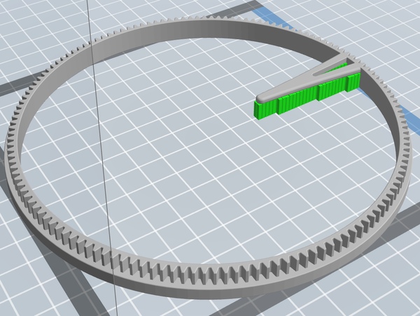
All parts should be printed at .2mm layer hight.
For the gears: All of them should be printed in black.
For the other parts: All of them should be printed in white, and only minutes ring and hours ring need support.
The images show where support is required on the parts.
Frame C should be printed twice.
Step 2: Cut the Brass Tubes
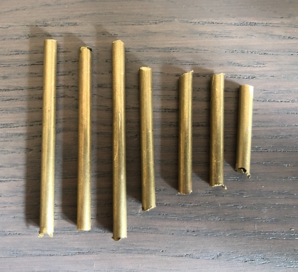
To cut the tubes, put the brass tube into the vise and cut it with a dremel.
The lengths of the tubes are:
45mm (make 3)
34mm (make 1)
25mm (make 2)
20mm (make 1)
Note: These are not the actual lengths of the tubes, but rather longer versions that will be sanded down later.
The video below shows how I cut the tubes using my Dremel 200.
Step 3: Sanding the Tubes
All of the tubes from the previous step should be sanded to the lengths below.
The 45mm tubes should be sanded to 41mm.
The 34mm tube should be sanded to 29.4mm.
The 25mm tubes should be sanded to 22.7mm.
The 20mm tube should be sanded to 17.7mm.
All of this should be done in a vise and with a dremel.
Step 4: Framework Assembly Pt. 1
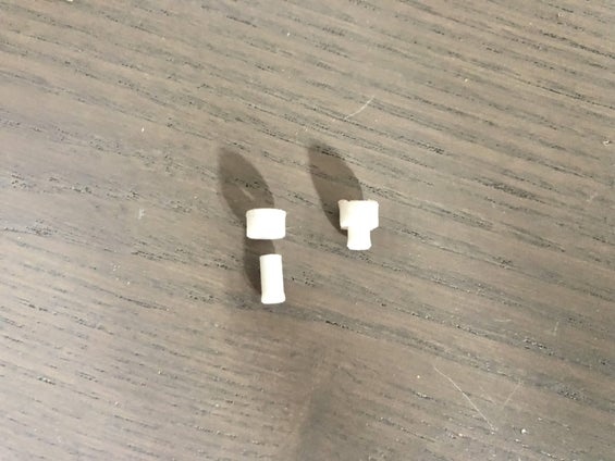
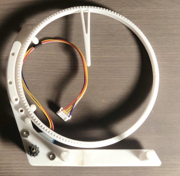
Glue the roller and roller shaft together and place it in one of the 3 holes on frame A with an arrow pointing to it and glue it in the hole. Repeat this 2 more times. Repeat this on frame B.
Step 5: Framework Assembly Pt. 2
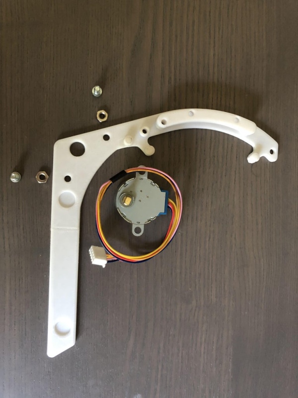
Using the pictures above as a guide, install the stepper motor into frame A using 2 M4 nuts and screws. After the motor is installed, take a small amount of masking tape and wrap it around the shaft of the stepper motor once. This will ensure that the shaft of the stepper motor will hold its gear tightly.
Step 6: Framework Assembly Pt. 3
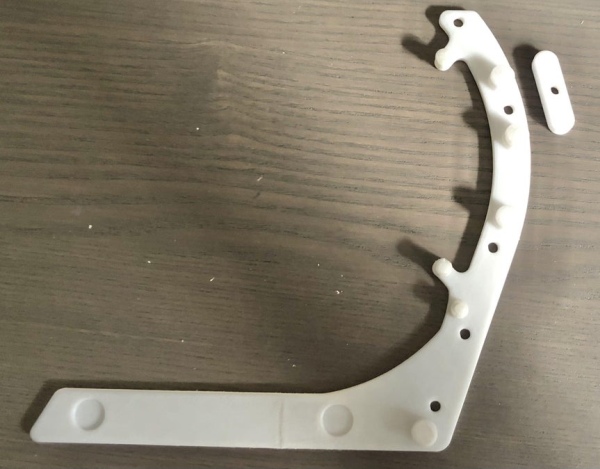
Inner frames A, B, and C can all be glued to the framework using the method depicted in the first 2 pictures. To put the inner frames on, you should use one of the brass tubes to stabilize the frame when you glue it on to one of the main frames. The last picture shows where each of the inner frames should be once they are glued on. Frame A is on the right and frame B is on the left.
Step 7: Framework Assembly Pt. 4
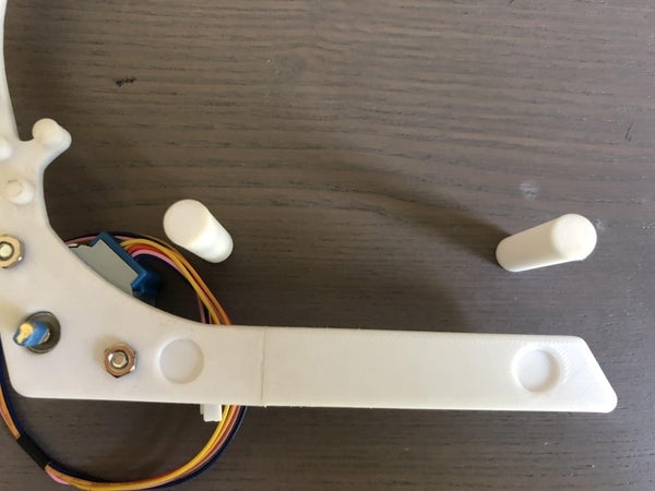
Glue both frame C parts into the indents in frame A.
Step 8: Gears Assembly
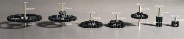
The photo above shows the tubes and the gears. Each gear is labeled. Directly above or below each shaft is its length. Next to each end of the shaft is the length of the amount of shaft protruding from the gear. Once you position the shaft, glue it in place. Repeat this for each gear.
Step 9: Adding the Gears
The pictures above show the order in which to add the gears. It also shows the assembly of 60t-10t with a roller and a large roller. Use the last pictures as a reference to see where the gears and washers should go.
IMPORTANT: Remember to put the minutes ring with frame A and the hours ring with frame B. Also remember to set the clock to 12:00 when you assemble it.
Step 10: Adding the Caps
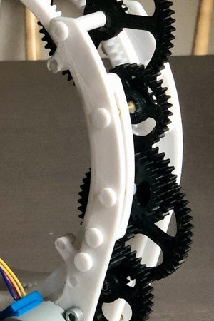
On each side of the clock there are 5 exposed brass tube ends. Glue a cap to each of the exposed ends.
Step 11: Adding the Circuits
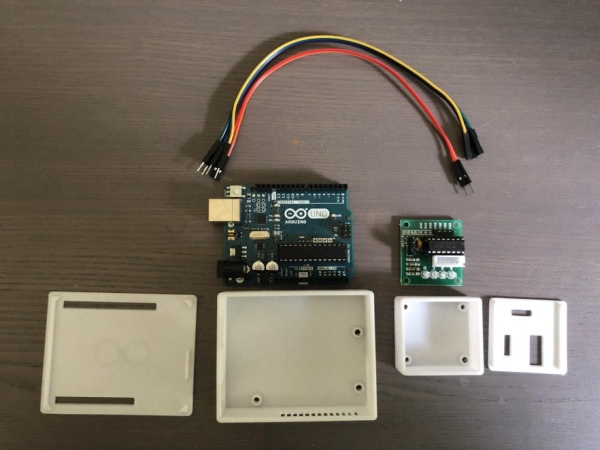
Screw the Adruino Uno in to its case using two screws. Do the same with the ULN2003 stepper motor driver.
There are several photos showing the positions of the wires on the board. Remember to connect the stepper motor to its driver.
Step 12: Arduino Code
Download the code below and and upload it to the board. Make sure the motor is rotating.
Step 13: Conclusion
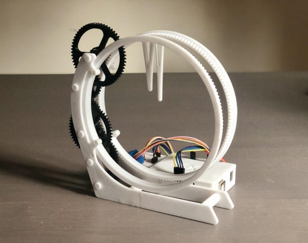
I really hope you enjoyed this project as much as I did.
If you have a questions, comments, or tips, please let me know.
I look forward to making more instructables in the future.
Below is a time-lapse of the clock running for fifteen minutes.
Source: 3D Printed Holo Clock With Arduino
-
How precise is the clock?
The clock keeps time very precisely. -
What software was used to design the parts?
The project was designed in OnShape over the course of a month. -
How should the layers be set during printing?
All parts should be printed at .2mm layer height. -
Which colors should be used for specific parts?
Gears should be printed in black, while other parts like the rings should be white. -
Why was masking tape used on the motor shaft?
A small amount of masking tape is wrapped around the shaft to ensure it holds its gear tightly. -
What is the correct assembly order for the rings?
The minutes ring must be attached with Frame A and the hours ring with Frame B. -
How many times should Frame C be printed?
Frame C should be printed twice. -
What tool is recommended for cutting the brass tubes?
A Dremel tool is used to cut the brass tube held in a vise.
