How to: Speaking Clock
Hello 🙂
Setup and Procedure
The wave shield is interfaced with the Arduino Mega 2560 as normal. A couple of pins were remapped because the wave shield was initially made for a different device. The DAC pins were remapped to pins 22,23,24 and 25 on the Arduino board. The WaveHC library also has to be modified to accommodate these changes. It is self-explanatory. The SD card communications pins MISO (Master-in-slave-out), MOSI (Master-out-slave-in), CS (chip select) and SCK (clock) are unchangeable and specific for every microcontroller used. For this project, they are pins 50,51,52 and 53. Refer to the pin mapping diagram for details.
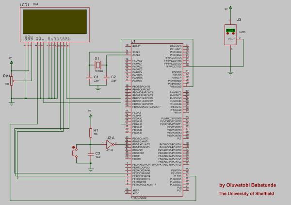
Only four data pins were connected from the LCD to the Arduino. This is the 4-bit data transfer mode. The 4-bit mode is efficient for simple alphanumeric data transfer. The RW (Read/Write) pin was grounded because data is only being sent to the LCD and not read from it. RV1 is contrast control for the LCD.
U2 is a hex Schmitt inverter IC used in this case for debouncing the button. The RC time constant = 0.1s which is good enough for the debounce. This could have also been achieved by software easily. Note: In my project, all the buttons were debounced using U2. Software debouncing could have been used as well, I only had a few problems doing that.
The sounds could have been achieved using a voice synthesizer but that incurs some cost. Instead, the sounds were recorded and converted to forms easy to process by the microcontroller.
Each individual audio track was recorded in Audacity and converted to WAV files understandable by the computer. The track properties were set to 16-bit PCM and rate was set to 22 KHz. It is not the best audio quality but the DAC can certainly handle the processing fairly well. The tracks were converted to mono because there is only one speaker. Stereo works but would be ambiguous and pointless.
An easy procedure is to record all the tracks on a single WAV file and export selected WAV’s. Every audio track is saved to the root directory on the SD card with relatively simple files names such as ’01.WAV’ for quick access to the root folder by the microcontroller.
The SD/MMC card must be formatted with the FAT file system before any recording is stored in it. FAT16 and FAT32 file systems are common and compatible with almost every system including cameras and microcontrollers.
*Check the English and Yoruba folders for recordings.
For more detail: Tag Archives: arduino speaking clock