Summary of WIRE CUTTING MACHINE
I built an automatic wire cutting machine controlled by an Arduino Nano that accepts user input (wire length and quantity) via push buttons, displays data on a 16x2 LCD, feeds wire with a stepper motor, and cuts to quantity using a servo-actuated cutter. PCB was designed in Fritzing and fabricated via JLCPCB; parts are soldered to the PCB and mounted on a 3mm acrylic base. Code is uploaded to the Nano; power is 12V for the stepper and USB for the Nano/servo.
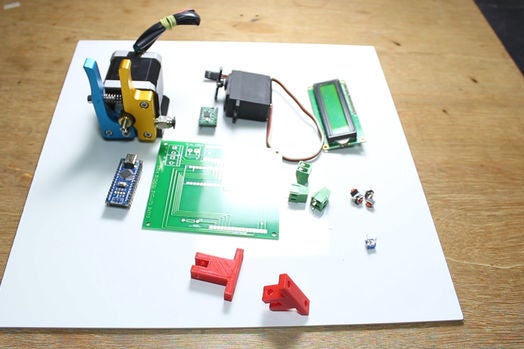
Parts used in the Automatic wire cutting machine:
- Arduino Nano
- Stepper motor
- A4988 motor driver
- 16 x 2 LCD
- Servo motor
- Cutter
- PCB terminal
- Push buttons
- Female header pins
- 3mm acrylic sheet (base)
Hello friends
I have made a Automatic wire cutting machine using Arduino nano controller board.
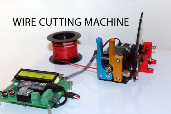
Basically there are 3 process level of this machine like
1) first process is Input
Input like wire length and wire quantity provided by pressing push button also the real time data can read on 16 X 2 LCD
2) Processing
all the inputs were processed by arduino nano and give command to stepper motor to feed required length of wire and instruct to servo to make cut of required quantity.
3) Output
Stepper motor, servo motor & cutter are the final output component
Step 1: Material Required
Followings are the material required
Arduino nano :- http://amzn.to/2Dcp2bK
Stepper motor :- http://amzn.to/2Dg6wycstepper
Motor driver :- http://amzn.to/2Dg6wycstepper
16 x 2 LCD :- http://amzn.to/2Db9LYA
Servo motor :- http://amzn.to/2r5oejj
Cutter :- http://amzn.to/2D9X6oZ
PCB terminal :- http://amzn.to/2r8uCq7
Push buttons :- http://amzn.to/2D9XbsN
Step 2: PCB Design
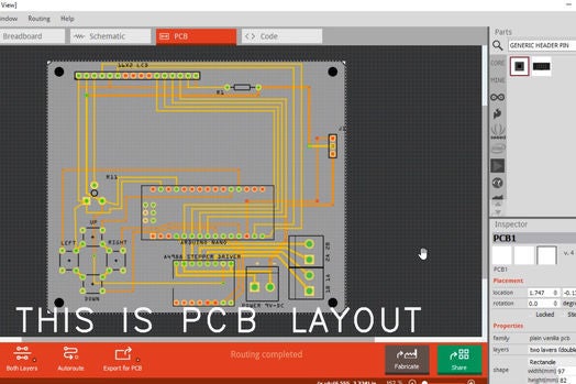
I have prepare PCB layout in fritzing software then Designe a PCB and export its gerber file
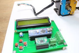
This gerber file uploaded to Jlcpcb.com to order the PCB as soon as you recived PCB you need to solder some female header pins to mount arduino nano, LCD display & A4988 driver also solder the PCB terminal to connect power supply to the PCB and to connect stepper motor to PCB here I attached the editable PLC layout file so if you can do any modification required.
https://drive.google.com/file/d/1iC4AMHDUVlfjNlICE…
Step 3: Procedure
So as soon as all the components are available you can start assembly the machine.
For the base of the machine I used 3MM thick white acrylic sheet
I drill some hole on sheet to mount PCB, Stepper motor with extruder set, cutter & servo motor for better idea please watch video it will give a idea how to mount those components on sheet all the components are tightly mount on the sheet now we can move to program our arduino
Step 4: Arduino Program
Upload the code to the arduino
Now connect the 12V DC at terminal of PCB this is for stepper motor and connect USB to arduino nano this will feed power to arduino itself and servo motor now machine is ready to perform you need to press those push buttons to navigate between screen and to select desire data hope you will like my this project
Source: WIRE CUTTING MACHINE
- How do you input wire length and quantity?
By pressing push buttons to navigate screens and select desired wire length and quantity, with real-time data shown on the 16 x 2 LCD. - What controller is used for the machine?
Arduino Nano is used to process inputs and control the motors. - How is the wire fed to the cutter?
The Arduino commands a stepper motor (via a driver) to feed the required wire length. - How is the wire cut after feeding?
A servo motor actuates the cutter to cut the wire to the required quantity. - What power supplies are required?
12V DC is connected to the PCB for the stepper motor; USB powers the Arduino Nano and the servo motor. - How was the PCB produced?
The PCB layout was made in Fritzing, gerber files exported, and the PCB ordered from JLCPCB; components are then soldered on. - What material is used for the machine base?
A 3mm thick white acrylic sheet is used as the base to mount components. - What needs to be soldered to the PCB?
Female header pins for Arduino Nano, LCD, and A4988 driver, plus PCB terminals for power and stepper connections. - Where can I find the PCB layout file?
The editable PCB layout file was shared via a Google Drive link in the article.