I have a major problem when it comes to talking on the phone or playing video games with my friends – I often get loud (that’s quite an understatement). Since I live with my parents, this often triggers my mother and she usually ends up barging into my room to tell me to quiet down. It is quite frightful especially when you have 5 of your friends on the other side of the call witnessing your embarrassment. I took this problem as an opportunity to solve an issue using engineering and also enhance my skills in codingI’ve always wanted to implement sound into my projects. It seemed like an interesting way to solve an issue (spoiler alert, it’s very frustrating but you won’t have to worry), so I decided to approach this problem by limiting how loud I can speak.
This project will work by using a sound sensor that is connected to an LCD display, an RGB LED, and an Arduino. We will set a certain threshold value on the sound sensor, and once that value is exceeded, the RGB LED will turn bright red, and a message will appear on an LCD display saying “You’re too loud!” or “Be quiet!” or if you want to be aggressive “Shut up!!”.
However, that’s not it just yet! Let’s make this project a tad bit more interesting. Visual cues are nice, but that will only weaken the problem – not solve it. There’s an old – and awful – training technique that is used on animals called fear conditioning. You can read more about it here. To sum it down, animals are conditioned to dislike certain things by associating with those said things with fear. For example, mice will be continuously shocked when they see a picture of bread, forcing them to believe that bread is evil and will harm the poor mice. You get the idea.
Now how can we incorporate this idea into the project? Simple! by shooting a nerf gun at the user when they get too loud! This will force the user to stay quiet and have to suffer actual consequences if they begin to raise their voice.
[DISCLAIMER]Shahmeer Khan is not responsible for any injury caused during or after the process of the creation of this project. This is meant to be something fun and not intended to hurt you or others. Please be careful when shooting projectiles at yourself.
Okay, let’s get to it!
Supplies
What you will need:
- 9 Volt Battery
- 9 Volt Battery Connector
- Arduino UNO REV3
- LCD Display (16×2)
- Sound Sensor (3 pin or 4 pin, as long as it has digital out)
- 10k Ohm Potentiometer
- 330 Ohms Resistor (x3)
- Jumper cables (As many as you can get a hold of)
- AND gate
- RGB LED (common anode)
- Solderless Breadboard
Optional (if you choose to add the nerf gun):
- Nerf gun (or any other type of dart shooter you have)
- 28byj 48 Stepper Motor
- H bridge (should be included with motor)
- 4 Male to Female cables (should be included in previous jumper cables link)
Step 1: Getting to Know Your Parts:
Assuming you are a complete noobie, I can walk you through the basics of how each of these components work. If you already know or just want to go straight into the building, you can skip to the next section.
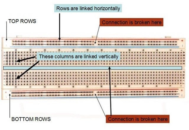
Breadboard
Since the breadboard is going to be the foundation of our entire circuit, it is a good idea that we understand how it works. A breadboard consists of a bunch of holes, where many of them are connected. We can place electronic components into these holes and create circuits. See the diagram above for an example. Often times, the side railings that are connected horizontally will be used as ground and power in order to keep things organized. We will do the same for this project.
RGB LED
RGB LEDs are also very interesting in how they work. An RGB LED works very similarly to a standard LED, but instead of one single colour, it can display almost any colour. This is because there are smaller LEDs all packaged together inside: red, green, and blue. These LEDs come in two variations: common cathode or common anode. A common cathode LED is where all the LEDs inside all share the same cathode in a single pin. A common anode is the same thing but instead with an anode pin. For this project, we will be using a common anode LED.
LCD DISPLAY
LCD displays (also known as liquid-crystal displays) have liquid crystals present within the screen. They use a special type of crystals that become completely opaque once current begins to flow through them. This is used within the LCD display to block any light that the backlight within the display emits, creating shapes, letters, etc. In this project, we will be using it to display information on our noise level.
Sound Sensor
Sound sensors are simple to understand, however, they could possibly be very frustrating to work with when they don’t function properly (I’m speaking from experience). The basic fundamentals of this sensor is combing a microphone with come circuitry and a built-in potentiometer that adjusts the sensitivity of the sensor. To learn more about this, you can read it here.
Stepper Motor
Stepper motors are very similar to DC motors, however, they move in very small increments which allows the user to make precise movements, while also having a lot of torque at their disposal. Within these stepper motors consist of numerous magnetic coils that are organized in sections called phases. When these phases are energized, it moves the internal shaft by a step, therefore rotating the shaft.
AND Gates
Logic gates are small chips that can take two values and provide a single output. AND gates are a type of logic gates that output a 1 or TRUE value when both inputs are TRUE.
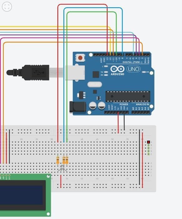
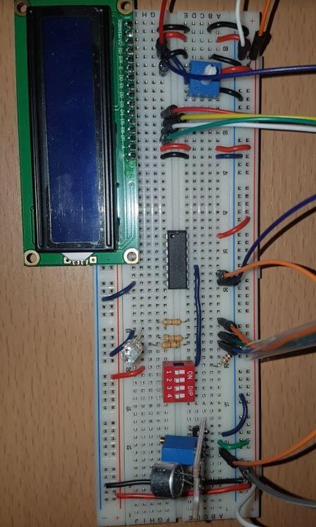
Step 2: BUILDING THE CIRCUIT: Preparing the Breadboard
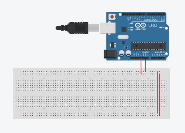
Before we start plugging things in, let’s provide both ground and power to our breadboard so the rest of the circuit can work.
- Attach a red jumper cable from the Arduino’s 5 volt pin on the left side of the Arduino, to the power rail of the breadboard.
- Attach a black jumper cable from the Arduino’s GND pin (should be below 5V) to the ground rail of the bread board.
- Connect both sides of the rails by using wires and connecting one power rail to the other, and same thing for the ground.
Step 3: Hooking Up the LCD Display
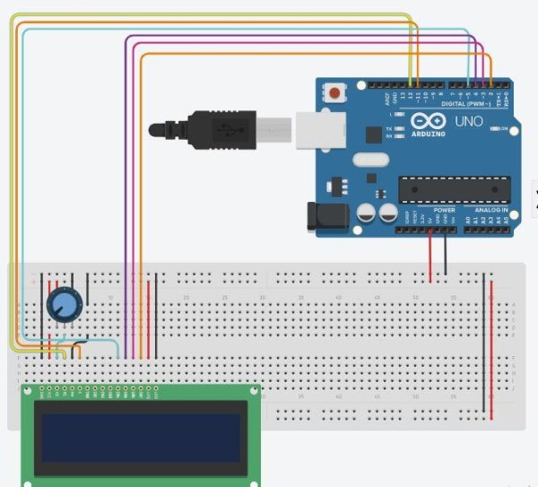
Connecting the LCD display is going to be the most wiring you will be doing for this project – so it is best to install this first.
The LCD display has 16 pins, but luckily for us, we only have to connect 12 pins. There’s a lot of wiring so just make sure you follow the schematic and the steps below.
- Place a potentiometer close to the LCD display.
- Attach one terminal leg of the potentiometer to power and the other terminal leg to ground.
- Hook the pins as stated below:
GND —– Ground rail
VCC —– Power Rail
V0 —– Middle pin of the potentiometer
RS —– Pin 12 on Arduino
RW —– Ground rail
E —– Pin 11 on Arduino
D4 —– Pin 5 on Arduino
D3 —- Pin 4 on Arduino
D2 —– Pin 3 on Arduino
D1 —– Pin 2 on Arduino
A —– Power Rail
K —– Ground Rail
Step 4: Attaching the RGB LED
The RGB LED is a bit tricky to work with if you aren’t paying attention.
- The pin that is the longest out of all of them is the common anode pin. That pin should be connected to power.
- The pin that is on the left of it (there should only be 1 pin on the left, if there are two, then flip your LED), that is your red pin and the one to the far right is your green and blue. Connect your red pin to a 330 Ohm resistor, and the green and blue to their own individual 330 Ohm resistor.
- Connect the Red pin to pin 13 on the Arduino.
- Connect the Green pin to pin 10 on the Arduino.
- Connect the Blue pin to pin 8 on the Arduino.
Step 5: Attaching the Sound Sensor
Attach the AND gate, switch, and sound sensor to the breadboard.
If you had bought the sound sensor that looked like the one I previously linked, then all you need to do is plug it into the breadboard. The sound sensor itself will have 4 pins that are individually labeled.
AND gate pin instructions:
Pin 14 —– Power
Pin 7 —– Ground
Pin 10 —– Middle Switch Pin
Pin 9 —— DO on Sound Sensor
Pin 8 —– Pin 6 on Arduino
Sound sensor Pin instruction:
G —– Ground
+ —– Power
DO —– Pin 9 on AND gate
Switch instructions:
Middle Pin —– Pin 10 on AND gate
Right leg —- 330 Ohm resistor —– Ground rail
Left leg —– Power
Step 6: Attaching the Stepper Motor
As you unpack the stepper motor, the first thing you should do is connect the female 5 pin connector to the H bridge. Then connect the following pins.INT1 —– A4
INT2 —– A3
INT3 —— A2
INT4 —— A1
Gnd —– Ground
+ —– Power
And that should be all the wiring that is required for you to do! However, there is still one more step.
Step 7: Attaching the Stepper to the Nerf Gun
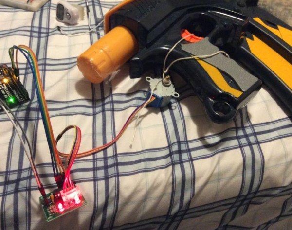
Finally, the part we have all been waiting for. Using a piece of string or rope, tie a bowline knot around the trigger, and then wrap the opposite end of the string to the shaft of the stepper. Make sure that the string is tight and there is a lot of tension so the rope can be pulled effectively. Here’s a video on how to tie a bowline knot that had helped me. Took me some trial and error but it eventually worked.
Step 8: Coding
The code is right below. Just copy and paste this and the code should work.
NOTE: If your trigger requires more pressure to pull, update the stepper value.
define sensorPin 6
#include#include
#define STEPS 32
LiquidCrystal lcd(12, 11, 5, 4, 3, 2);
unsigned long lastEvent = 0;
Stepper stepper (STEPS, A4, A2, A3, A1);
int redPin = 13; int greenPin = 9;
void setup() { pinMode(sensorPin, INPUT); Serial.begin(9600); lcd.begin(16, 2); pinMode(redPin, OUTPUT); pinMode(greenPin, OUTPUT);
stepper.setSpeed(200);
}
void loop() {
int sensorData = digitalRead(sensorPin);
if (sensorData == LOW){
digitalWrite(redPin, LOW);
digitalWrite(greenPin, HIGH);
Serial.println(“Sound Detected!”);
lcd.clear();
lcd.setCursor(0,0);
lcd.print(“Shhh”); // custom message can go here
stepper.step(-1000); //Adjust this to make the stepper motor turn more or less
delay(1000);
stepper.step(1000); //make sure this is the same value but positive
lcd.clear();
}
else{
digitalWrite(redPin, HIGH);
digitalWrite(greenPin, LOW);
}
}
Source: DIY: ARDUINO SOUND SENSOR SYSTEM