Summary of How to Use the RPLIDAR 360° Laser Scanner With Arduino
Summary: This tutorial explains how the RPLIDAR A1 360° laser scanner works and how to interface it with an Arduino (preferably boards with multiple hardware serial ports like Arduino M0/Zero). It shows installing the robopeak RPLIDAR library, wiring UART and motor control, and building a demo that visualizes distance data on a 24-LED ring mounted to the LIDAR. The guide includes required parts, a 3D-printed mount, and links to example code and videos.
Parts used in the RPLIDAR LED Ring Project:
- RPLIDAR A1 360° Laser Scanner
- Arduino M0 / Zero (SAMD21)
- Breadboard
- Jumper wires
- 5V external power supply
- 24 LED ring (24 LEDs, inner diameter ~70mm)
- 3D printed mount (Thingiverse model)
- M2.5 screws (optional) or hot glue for mounting
- Soldering tools/wires for LED ring
I enjoy creating sumo robots and am constantly searching for innovative sensors and materials to improve the speed and intelligence of my robots. I discovered the RPLIDAR A1, available for $99 on DFROBOT.com. I mentioned my interest in testing the sensor, and they offered me the opportunity to test it out. Once I obtained the LIDAR, I discovered that it is too costly to be used in the upcoming competition I intend to participate in.
In this tutorial I’ll give you a basic understanding of how this sensor works and how you can use it with an arduino.
Step 1: LIDAR What?
Wikipedia had two different meanings for LIDAR:
– LIght Detection And Ranging
– Laser Imaging Detection And Ranging
In general it can be seen as a distance sensor on a rotating base, which samples range data while continuously rotating. For each successful sample the measured distance is sent with the according angle.
In this case the data is sent over UART.
Step 2: Using an Arduino to Interface With the LIDAR
The connection between the LIDAR and the Arduino’s hardware serial port (UART) must be established, which prevents the UART data from being sent to the serial console in a simple Arduino setup. Because they only have one Serial port. An additional software serial port can be added to improve basic Arduino models with only one hardware serial port. The library described in this manual does not yet offer assistance for a software serial port.
To debug and send serial data to the serial console, you will need an Arduino with multiple Serial ports. Examples include: Arduino Mega, Arduino M0 / Zero using SAMD21 chipset.
If there is no need to upload information for debugging purposes, you have the freedom to choose any Arduino board.
In this manual, I will showcase a more sophisticated version of Arduino – the Arduino M0 / Zero, which is equipped with the SAMD21 microcontroller.
Needed components:
- Arduino M0 ebay link
- Breadboard ebay link
- jumper wires ebay link
- 5V power supply ebay link
- 24 Led ring ebay link
- First you’ll need to install the RPLIDAR library from robopeak:
https://github.com/robopeak/rplidar_arduino, this library offers 2 interesting examples on how to use the LIDAR. You can find more information on how to install a library in the arduino IDE in this article: https://www.arduino.cc/en/Guide/Libraries - Now open the “simple_connect” example code that is included in the library.
- Make the necessary hardware connections from the LIDAR to the arduino:
– Connect the RPLIDAR’s serial port (RX/TX/GND) to your Arduino board (Pin 0 and Pin1)- Connect the RPLIDAR’s motor ctrl pin to the Arduino board pin 3
– Use an external 5V power supply to power the motor control pin and the LIDAR. - In the void setup you’ll have to change following code: “lidar.begin(Serial);” according to the used serial port. When using an Arduino M0 you should change “Serial” to “Serial1”. This can be different for other Arduino’s.
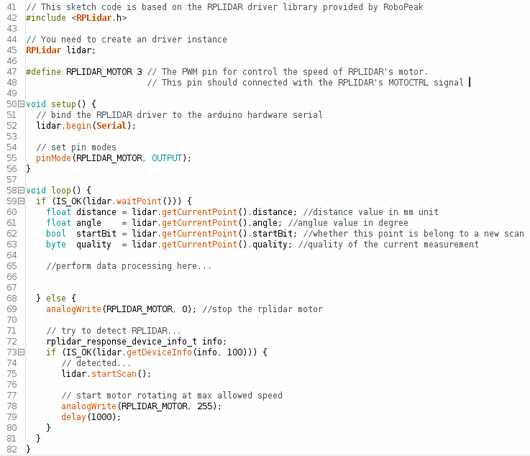
- The first picture is what the example sketch should look like, lines 60-63 contain the variable names which you can use to get the data from the LIDAR.
- If you want to know what this data looks like you can print this data to the serial monitor, with the code in the second picture.
In the following step we’ll make a very basic working project with the LIDAR and a LED ring.
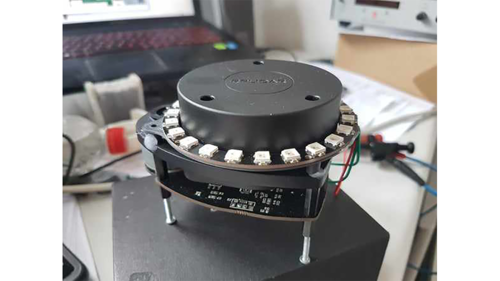
Step 3: Making the LIDAR LED Ring Project
For this task, we will attach a controllable LED ring to the LIDAR. In this manner, we are able to represent the LIDAR information graphically.
In this particular program, the LED will be activated towards the nearest detected signal.
Watch this video at the following link: https://youtu.be/L1iulgiau0E
The project’s code is derived from a sample provided by robopeak.
https://github.com/robopeak/rplidar_arduino/tree/m…
The changed code for this project is included in the zip file in this step.
Needed parts:
– LED ring: with 24 LEDS big enough to fit over the LIDAR, inner diameter 70mm
– Arduino Zero
– LIDAR
– Separate 5V power supply
– 3D printed part: https://www.thingiverse.com/thing:3185216
- Get all the needed parts
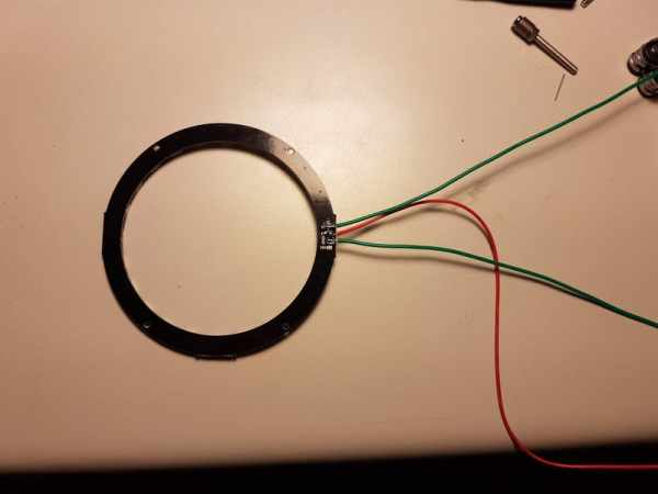
- Solder the wires to the LED ring
- Glue the LED ring to the 3d printed part
- Mount the 3D printed part onto the LIDAR, there are holes in the 3Dprinted part for M2.5 screws but I didn’t had them laying around to I just used hot glue
- Connect the wires from the LIDAR to the arduino:
GND -> GND
5V -> 5V of separate power supply
Di -> pin D5 of arduino - Upload the sketch and power up the external power supply
Final result can be viewed here on youtube:
Source: How to Use the RPLIDAR 360° Laser Scanner With Arduino
- What does LIDAR stand for?
According to Wikipedia, LIDAR can mean Light Detection And Ranging or Laser Imaging Detection And Ranging. - Can I use a basic Arduino with one hardware serial port?
You can use any Arduino if you do not need serial debugging, but the library does not support SoftwareSerial; for debugging use a board with multiple hardware Serial ports like Arduino M0/Zero or Mega. - How do I connect the RPLIDAR to the Arduino?
Connect RPLIDAR RX/TX/GND to Arduino serial pins (Pin 0 and Pin 1 for hardware Serial), connect the motor control pin to Arduino pin 3, and power the LIDAR and motor with an external 5V supply. - Which Arduino Serial object should I use on Arduino M0/Zero?
On Arduino M0/Zero change lidar.begin(Serial) to lidar.begin(Serial1). - Which library should I install to use the RPLIDAR with Arduino?
Install the robopeak RPLIDAR Arduino library from https://github.com/robopeak/rplidar_arduino. - What does the LED ring project display?
The LED ring lights toward the nearest detected signal to graphically represent LIDAR distance data. - What size LED ring is required for the project?
A 24 LED ring with an inner diameter around 70mm, large enough to fit over the LIDAR, is used. - Is a 3D printed part required?
Yes, a 3D printed mount from Thingiverse (thing:3185216) is used to attach the LED ring to the LIDAR. - Do I need to solder the LED ring wires?
Yes, soldering wires to the LED ring is listed as a required step before connecting to the Arduino. - Where can I find the example sketch used for the project?
The project code is based on a robopeak sample included in the rplidar_arduino library and the modified sketch is provided in the tutorial zip linked in the article.