
Summary of ESP8266 VGA Pong
This article details the construction of a Pong game reproduction for VGA monitors using an ESP8266 microcontroller and the EspVGAx library. It achieves a high resolution of 512x480 pixels, significantly surpassing previous Arduino-based VGA solutions. The guide covers material selection, software configuration via Arduino IDE, circuit assembly involving VGA connectors and input devices, and code upload instructions to create a functional retro gaming device.
Parts used in the ESP8266 VGA Pong Project:
- ESP8266 NodeMCU-12E board
- DSUB15 connector (VGA female connector)
- 330 Ohm Resistor
- Resistor between 1 to 3 kOhm
- Two 10 kOhm Potentiometers
- Push Button (n.o.)
- Two Diodes (such as 1N4007s)
- Breadboard
- Wires
In this Instructables I will show how to build a reproduction of the the classic game Pong for a VGA monitor, using a ESP8266 and few other components.
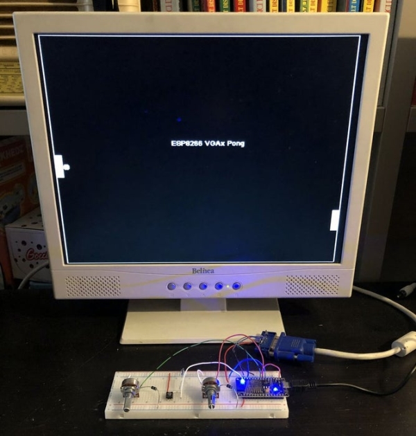
This game is made possible by the EspVGAx library recently published on GitHub by Sandro Maffiodo (aka Smaffer) and, as far as I know, this is the first game exploiting it.
The library implements a resolution of 512 x 480 pixels, stored in a framebuffer inside the RAM, which requires 30720 bytes. The resolution is huge in comparison to the Arduino TVout or VGAx ones (128 x 96 and 120 x 60 pixels respectively). I hope this game inspires other programmers to develop or reproduce more complex games.
Step 1: List of Materials
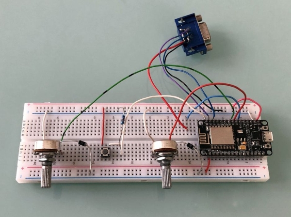
The EspVGAx library requires an ESP8266 with all GPIO exposed, like ESP-12E, NodeMCU-12E board or any board that expose GPIO5 (D1), GPIO4 (D2) and GPIO13 (D7)
In particular, I used:
- an ESP8266 NodeMCU-12E (link here)
- a DSUB15 connector (i.e. a VGA female connector)
- a 330 Ohm Resistor
- another resistor (about 1 to 3 kOhm)
- two 10 kOhm Potentiometers
- a Push Button (n.o.)
- two Diodes (such as 1N4007s)
- a breadboard
- wires
I got the DSUB15 connector from an old VGA PC board. Alternatively, you can also cut an old VGA cable and connect the wires directly to the breadboard.
Step 2: Library and Sketch Upload
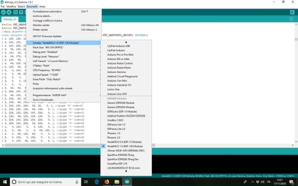
There are different methods to program and ESP8266; I used the Arduino IDE to write Pong and upload the code.
Please note that the EspVGAx library works for Arduino IDE 1.8.1. If you have other versions, the best is to dowload the .zip files and uncompress it in a dedicated folder. The Windows version is here. Versions for other OS are here.
After that, you should dowload the EspVGAx library from the GithHub page here (direct link for the zip version here), and uncompress it in the folder libraries in the Arduino software.
NB There is a little bug in the file espvgax_draw.h. To correct it, just replace the line 17:
while (x0%32) { with while (x0%32 && sw > 32) {
Finally you can dowload ESP8266_Pong.rar at the end of this step.
Once unzipped, to upload it on your ESP8266, you need to configure the Arduino IDE.
If you have never done it, you can find all the needed instruction on this Instructables, in particular in Step 2.
Once everything is configured, the ESP8266 settings should look like the ones shown in the picture above.
If you can upload the code without errors, you can start to assemble the parts.
Step 3: Connecting the Parts: the VGA Connector
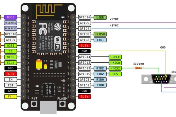
I reccomand to connect first the VGA port, as shown in the pictures above. Please note that by connecting the three pins Red, Green and Blue together (i.e. pins 1, 2 and 3 on the DSUB15 connector), you will have a B&W image on your screen. You can also have different colors combination. See the details on the Library GitHub page.
Furthermore, you should connect a 330 Ohm resistor between the RGB pins and the D7 (GPIO13) on the ESP8266. This gave me a bit greyish image on my monitor thus, after few tries, I decided to eliminate it at all.
At this point, if everything works properly, you can already connect the monitor and see the beginng screen of the game, with the banner “ESP8266 VGAx Pong“.
Step 4: Connecting the Parts: the Potentiometers and Button
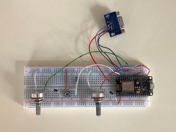
The button must be connected between 3.3V and pin D0 (GPIO16). Connect also the 1 to 3 kOhm resistor from D0 to ground. This avoids D0 to be at an undetermined status when the button is open.
The connection of the two potentiometers is less trivial, as a matter of fact the ESP8266 has only an analogue input port A0 (ADC0)! The trick is to connect both pot.s outputs to the same port, and ‘multiplex’ them. Multiplexing simply means that you will turn a potentiometer on, read it, then turn it off and move to the second one.
If you want to learn more about this method, you can read this Instructable.
Connect one potentiometer extreme to GND, the other extreme to D5 for the left player potentiometer and D6 for the right player one.
Each potentiometer central pin must the connect to an individual diode, and the other sides of the diodes must be connected to A0 (ADC0), with the polarity shown in the above picture.
Step 5: Conclusion and Acknowledgments
I am grateful to Sandro Maffiodo – SMAFFER – for the ESPVGAX libary. This game would not be possible without it.
I hope this Instructable will be an inspiration to other programmers to make reproductions of more complex classical arcade games with the ESP8266, which has much less limitation than the Arduino.
Finally, I wrote this Instructable to submit it to the Toys Contest: if you like or reproduce it, please take a moment to vote it!
Source: ESP8266 VGA Pong
-
What components are required to build this project?
You need an ESP8266 with exposed GPIOs like NodeMCU-12E, a DSUB15 connector, various resistors, two potentiometers, a push button, two diodes, a breadboard, and wires. -
How does the resolution of this project compare to other libraries?
This project uses a resolution of 512 x 480 pixels, which is huge compared to Arduino TVout (128 x 96) or VGAx (120 x 60). -
Which Arduino IDE version is compatible with the EspVGAx library?
The library works for Arduino IDE 1.8.1; for other versions, users should download the .zip files and uncompress them in a dedicated folder. -
Is there a known bug in the library that needs fixing?
Yes, line 17 in the espvgax_draw.h file contains a bug that must be corrected by replacing specific while loop conditions. -
How can I get a black and white image on the screen?
By connecting the three pins Red, Green, and Blue together on the DSUB15 connector, you will have a B&W image. -
Why was the 330 Ohm resistor removed from the final design?
The author decided to eliminate it after trying it because it resulted in a greyish image on the monitor. -
How do you connect two potentiometers when the ESP8266 has only one analog input?
You multiplex them by connecting both outputs to the same port A0, turning one on to read it, then turning it off to read the second one. -
Which GPIO pin is used for the push button input?
The button connects between 3.3V and pin D0 (GPIO16), with a pull-down resistor to ground.
