
Summary of Home Presence Simulator and Security Control Device
This project creates a home security system that simulates occupancy and detects movement using a network of Arduino-controlled devices. A master device coordinates multiple slave units, managing scheduled light switching and IR signals for appliances while sending email alerts upon motion detection. The system features remote configuration via a web server and utilizes wireless communication between nodes.
Parts used in the Home Presence Simulator:
- Electric box
- ARDUINO NANO or compatible ARDUINO NANO microcontroller
- ARDUINO MEGA 2560 R3 or compatible ARDUINO MEGA 2560 R3 microcontroller
- WiFi NodeMCU Lua Amica V2 ESP8266 module
- RTC DS3231 module
- Protoboard 480
- Protoboard 170
- Relay
- 38 KHz IR transmitter
- PIR sensor
- nRF24L01 module + antenna
- Adapter for nRF24L01 module
- Power supply 5V, 0.6 A
- Lamp holder
- Light bulb
- Cables
- Terminal block
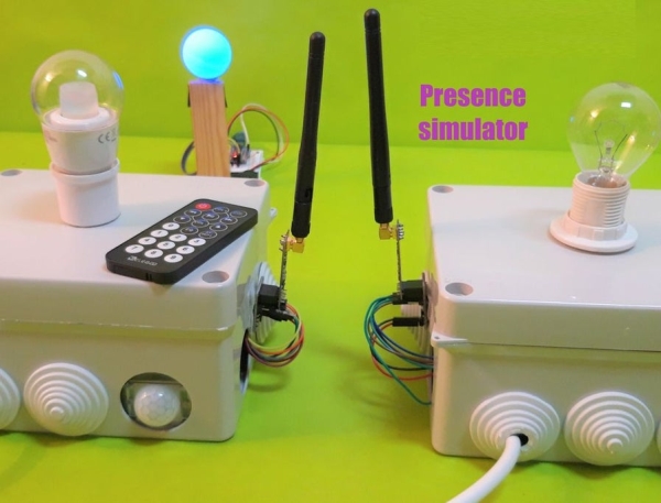
This project allow us to simulate presence and to detect movements in our home.
We can configure a network of devices installed in differents rooms of our home all of them controlled by a main device.
This project combines these features on a single device (PICTURE 1):
- It is a presence simulator: the device switchs on and off one light bulb (PICTURE 1) and use an IR transmitter (PICTURE 2) to send 38 KHz IR control codes to IR controlled devices (TV, VCR, lamps, …)
- It is a movement detector: the device has got a PIR sensor to detect movements (PICTURE 3)
The whole system is controlled by a master device that send signals to the others slave devices presents in the network to switch on and off the lights and to activate controlled IR devices according to a scheduled presence simulation.
The main features of the master device are the following:
- It uses a scheduled secuence of commands to control each slave device. For example: the light in the slave station 1 will switch on every day during a random period of time or the slave station 2 will switch on the TV and will change channel after a period of time.
- It receives the signals from the slave stations when a movement is detected and send us and e-mail
- It configures a Web Server to control and update the whole system remotely from the Cloud
I hope you like and be useful for somebody.
Step 1: Building a Slave Device
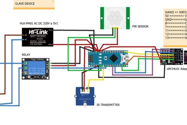
To build a slave device we will need the following:
- Electric box
- ARDUINO NANO or compatible ARDUINO NANO microcontroller
- Protoboard 480
- Relay
- 38 KHz IR transmitter
- PIR sensor
- nRF24L01 module + antenna
- Adapter for nRF24L01 module
- Power supply 5V, 0.6 A
- Lamp holder
- Light bulb
- Cables
- Terminal block
The steps to mount it are the following (see the Fritzing drawing for each pin connection):
- PICTURE 1: open a hole in the electric box for the lamp holder
- PICTURE 2: install the protoboard 480 with the NANO microcontroller, the IR transmitter and the power supply
- PICTURE 3: connect the phase conductor of the lamp holder to the NC terminal of the relay and the neutral conductor to the neutral input in the terminal block. After that, connect the common terminal of the relay to the phase conductor of the input in the terminal block
- PICTURE 4: connect the IR transmitter and the PIR sensor to the NANO microcontroller. See the step 3 to configure the IR codes for the device you want to control
- PICTURE 5: install the nRF24L01 adapter outside the electric box and connect it to the NANO microcontroller. As you can see in this picture the cables goes into the electric box through a hole that also it is used to connect the USB programming cable to the NANO microcontroller
Step 2: Building the Master Device
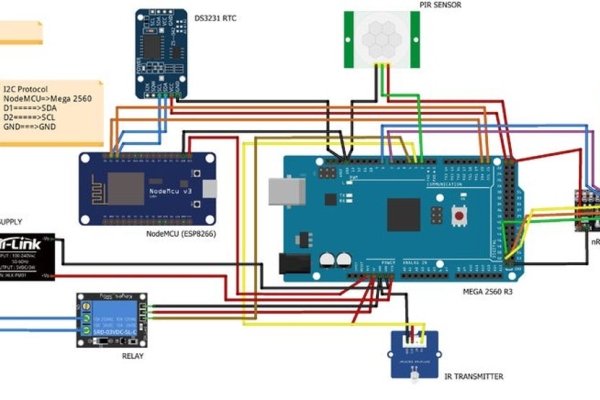
To build the master device we will need the following:
- Electric box
- ARDUINO MEGA 2560 R3 or compatible ARDUINO MEGA 2560 R3 microcontroller
- WiFi NodeMCU Lua Amica V2 ESP8266 module
- RTC DS3231
- Protoboard 170
- Relay
- 38 KHz IR transmitter
- PIR sensor
- nRF24L01 module + antenna
- Adapter for nRF24L01 module
- Power supply 5V, 0.6 A
- Lamp holder
- Light bulb
- Cables
- Terminal block
The steps to mount it are very similar to the previous one because the master device is essentially a slave device with more features (see the Fritzing drawing for each pin connection):
- PICTURE 1: open a hole in the electric box for the lamp holder
- PICTURE 2, PICTURE 3: install the ESP8266 module in the protoboard 170 and place it over the MEGA 2560 microcontroller as you can see in the pictures
- PICTURE 4: paste a piece of wood inside the eletric box. Over the piece of wood install the MEGA 2560 microcontroller with the ESP8266, the clock module DS3231 and the nRF24L01 adapter
- PICTURE 5: install the power supply and the realy. Connect the phase conductor of the lamp holder to the NC terminal of the relay and the neutral conductor to the neutral input in the terminal block. After that, connect the common terminal of the relay to the phase conductor of the input in the terminal block.
Step 3: Configuring the Master and Slave Devices
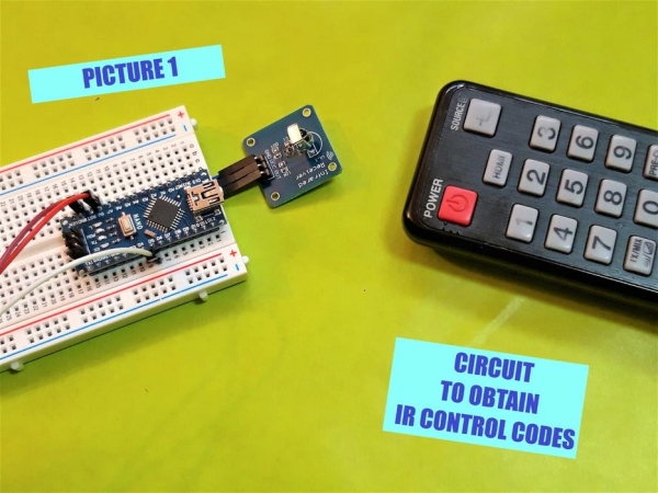
To configure the devices you have to do the next steps:
STEP 3.1 (both devices)
Install the IRremote, RF24Network, RF24, DS3231 and Time libraries in your ARDUINO IDE
STEP 3.2 (only for a slave device)
Configure the address in the network. Just only look for the following code in the sketch “presence_slave.ino” and give an address in octal format. Only use addresses greater than 0 because the address 0 is reserved for the master device
const uint16_t this_node = 01; // Address of our slave device in Octal format
Load the sketch “presence_slave.ino” into the microcontroller.
STEP 3.3 (only for a master device) (INTRODUCING IR CONTROL CODES)
If you are going to use a device controlled by 38KHz IR controls codes to simulate presence, you have to know some of them.
Otherwise, you have to obtain the IR control codes from your device.
To do that, you will need a 38KHz IR receiver, load in one NANO microcontroller the sketch “ir_codes.ino” and connect everything as you can see in the PICTURE 1
Then, point your remote control to the IR receiver, push any button and you will see in the serial monitor something similar to:
(12 bits)Decoded SONY: A90 (HEX) , 101010010000 (BIN)	// POWER button
(12 bits)Decoded SONY: C10 (HEX) , 110000010000 (BIN)	// 4 button
(12 bits)Decoded SONY: 210 (HEX) , 1000010000 (BIN)	// 5 button
In this case the remote control uses the SONY IR protocol and when we push the power button on the remote control we obtain the IR code “0xA90” of lenght 12 bits or when we push the button 4 on the remote control, we obtain the IR code “0xC10”.
I recommend at least look for the power and several button numbers IR control code to simulate presence.
After you have obtained the IR codes before, you have to introduce them in the following way:
FIRST WAY
If you have configurated a wifi network you can do it using the web page (See the step: The Web Server)
SECOND WAY
Otherwise, you have to look for the next code in the file “ir_codes.ino” and update the information. In the code below you can see how we can introduce the information obtained above only for the master device (address = 0)
/******************************************/
/******* IR control codes *****************/
/******************************************/
// protocol_id, number_of_bits, 10 IR control codes for the master device (address = 0)
SONY,12,0xA90,0xC10,0x210,0,0,0,0,0,0,0,
// protocol_id, number_of_bits, 10 IR control codes for the slave device (address = 1)
UNKNOWN,0,0,0,0,0,0,0,0,0,0,0,
// protocol_id, number_of_bits, 10 IR control codes for the slave device (address = 2)
UNKNOWN,0,0,0,0,0,0,0,0,0,0,0,
// protocol_id, number_of_bits, 10 IR control codes for the slave device (address = 3)
UNKNOWN,0,0,0,0,0,0,0,0,0,0,0,
// protocol_id, number_of_bits, 10 IR control codes for the slave device (address = 4)
UNKNOWN,0,0,0,0,0,0,0,0,0,0,0
/*********************************************/
/********* End IR control codes **************/
/*********************************************/
The sketch is configurated to works with the following IR protocols:
- NEC
- SONY
- RC5
- RC6
- LG
- JVC
- WHYNTER
- SAMSUNG
- SHARP
- DISH
- DENON
- LEGO_PF
In the file “ir_codes.ino” you can find some IR control codes for SAMSUNG and SONY protocols.
/***************************************************************************/
// SOME IR_PROTOCOLS AND CODES
// (SAMSUNG,number_of_bits,button POWER,button 1,2,3)
// SAMSUNG,32,0xE0E010EF,0xE0E020DF,0xE0E0609F,0xE0E0A05F
// (SONY,number_of_bits,button POWER,button 1,2,3,4,5,6,7,8,9,0)
// SONY,12,0xA90,0x010,0x810,0x410,0xC10,0x210,0xA10,0x610,0xE10,0x110,0x910
/**************************************************************************/
IMPORTANT: the first IR control code introduced must be the IR control code to switch off the device. It will be sent by the master to the slaves when there is not any action planned for that device.
If some body knows or somebody has obtained some IR control codes of some of the protocols listed above, please post a comment in this instructable with the following information: protocol id, protocol length and IR control codes.
STEP 3.4 (only for the master device) (INTRODUCING THE PRESENCE SIMULATION PLANNING)
You can introduce the presence simulation planning in the following way:
FIRST WAY
If you have configurated a wifi network you can do it using the web page (See the step: The Web Server)
SECOND WAY
You have to look for the next code in the file “ir_codes.ino” and update the information.
The presence simulation planning format is the following:
(hour_init_interval1) , (hour_end_interval1) , (hour_init_interval2) , (hour_end_interval2) ,(min_delay_ir) , (max_delay_ir) , (min_delay_light) , (max_delay_light)
/************ PRESENCE SIMULATION PLANNING ************/
7,8,17,3,5,60,10,40,      // master device (address = 0)
0,0,17,23,3,30,5,10,      // slave device  (address = 1)
0,0,0,0,0,0,0,0,          // slave device  (address = 2)
0,0,0,0,0,0,0,0,          // slave device  (address = 3)
0,0,0,0,0,0,0,0           // slave device  (address = 4)
/************ END PRESENCE SIMULATOR ********************/
In the example above the presence simulation planning for the master device is the following:
- (hour_init_interval1 = 7) The first interval simulation will begin at 7:00 a.m. everyday
- (hour_end_interval1 = 8) The first interval simulation will end at 8:00 a.m. of the same day
- (hour_init_interval2 = 17) The second interval simulation will begin at 17:00 p.m. everyday
- (hour_end_interval2 = 3) The second interval simulation will end at 3:00 a.m. of the next day
- (min_delay_ir = 5) (max_delay_ir = 60) The delay time in minutes between random sendings of IR control codes is a random number between 5 and 60
- (min_delay_light = 10) (max_delay_light = 40) The delay time in minutes between the light switch on and off is a random number between 10 and 40
and the presence simulation planning for the slave device with address 2 is the following:
- (hour_init_interval1= 0) There isn´t first interval simulation defined
- (hour_end_interval1 = 0) There isn´t first interval simulation defined
- (hour_init_interval2 = 17) The simulation will init at 17:00 p.m. everyday
- (hour_end_interval2 = 23) The simulation will end at 23:00 p.m. of the same day
- (min_delay_ir = 3)(max_delay_ir= 30) The delay time in minutes between random sendings of IR control codes is a random number between 3 and 30
- (min_delay_light = 5)(max_delay_light= 10) The delay time in minutes between the light switch on and off is a random number between 5 and 10
STEP 3.5 (only for the master device) (CONFIGURING THE REAL TIME CLOCK)
One of the key of this proyect is the time. We need to set the time of the ARDUINO when the sketch begins to run. To do that we need a real time clock module. One clock module is the DS3231 which support is a backup battery trickle charger, which can be used unless being connected to the microcontroller with three data cables using the I2C protocol.
Previous to use the DS3231 you have to set the time in this module. To do that, you have to run in the master device the sketch “DS3231_set.ino”.
STEP 3.6 (only for the master device) (CONFIGURING THE ESP8266 MODULE)
The sketch running in this module try to connect to your local wifi network and configure a web server.
So we need to update the following information in the sketch “presence_web.ino” to access to your local wifi network and to configure the Gmail e-mail address from where the ESP8266 is going to send the movements detected by all the devices in the network and the e-mail address where you want to receive the notifications (ESP8266 Gmail Sender instructable)
const char* ssid = "ssid of your local wifi network";
const char* password = "password of your local wifi network";
const char* to_email = "e-mail where you want receive notifications of movement detections";
WiFiServer server(80); // the port used to listen
and the following information in the sketch “Gsender.h”.
const char* EMAILBASE64_LOGIN = "*** your Gmail login encode in BASE64 ***";
const char* EMAILBASE64_PASSWORD = "*** your Gmail password encode in BASE64 ***";
const char* FROM = "*** your gmail address ***";
IMPORTANT: this code doesn’t work with ESP8266 core for Arduino version 2.5.0. For a temporary solution use core version 2.4.2
STEP 3.7 (only for the master device)
After doing the previous step 3.3, 3.4, 3.5 and 3.6 load the sketch “presence_master.ino” in the NANO microcontroller and the sketch “presence_web.ino” in the ESP8266 module
Step 4: Testing the System
To test if everything works as we want, the sketch “presence_master.ino” can run in test mode.
You can test a specific device in two ways:
FIRST WAY: if you don´t use a wifi network, you have to look for the next code in the file “presence_master.ino”, change to “true” the initial value for the “bool_test_activated” variable and update the address of one device to test in the next code line and load the sketch into the ARDUINO microcontroller in the master device.
boolean bool_test_activated = false;		// change to true to init test mode
int device_to_test = 0;				// slave device address to test
Don´t forget to change the value to false when you want exit the test mode and reload the sketch
SECOND WAY: If you use a wifi network, you can use the web page to activate the test mode. See the step “The Web Server”
If the device to test is going to send IR control codes, place the master or slave device in front of the IR controlled device (TV, radio …).
This mode works in the following way:
- TESTING THE LIGHT. The light of the specific device must switch on and off every 10 seconds.
- TESTING THE IR CODES. The sketch will choose randomly a IR code previously introduced and it will send to the IR controlled device every 10 seconds. So you have to test if that device is doing the action corresponding to the IR code received
- TESTING THE MOVEMENT DETECTOR. If the device detects movement in front of its PIR sensor, it will send the signal to the master device and its light must begin to flash several times
In the video at the end of this instructable you can see the test mode running.
Read more: Home Presence Simulator and Security Control Device
- How do I obtain IR control codes for my devices?
You must use a 38KHz IR receiver connected to an ARDUINO NANO running the ir_codes.ino sketch, then point your remote at the receiver to view codes in the serial monitor. - Can I configure the system remotely without a physical connection?
Yes, by configuring a WiFi network and a Web Server on the master device, you can update settings and view data from the Cloud. - What happens when a slave device detects movement?
The slave station sends a signal to the master device, which then sends an email notification to the user. - How is the time synchronized across the devices?
The master device uses a DS3231 real-time clock module with a backup battery to set the correct time before the sketch runs. - Does the system support different IR protocols?
Yes, the software supports protocols including NEC, SONY, RC5, LG, JVC, WHYNTER, SAMSUNG, SHARP, DISH, DENON, and LEGO_PF. - How do I define the presence simulation schedule?
You define start and end times for intervals along with random delay ranges for lights and IR codes within the code file for each device address. - Is it possible to test the system components individually?
Yes, the master device sketch includes a test mode where you can activate specific devices to verify light flashing, IR code transmission, and PIR sensor responses. - Which library is required to handle the wireless network communication?
The RF24Network and RF24 libraries must be installed in the ARDUINO IDE to manage the node network. - Can I change the email notification settings after installation?
Yes, you must update the ssid, password, and Gmail credentials in the presence_web.ino and Gsender.h files to configure the sender and recipient addresses. - What is the role of the master device compared to the slave devices?
The master device controls the scheduled sequences, receives movement signals from slaves, and hosts the web server, while slaves execute the local commands.
