
Summary of Alexa Controlled Dog Feeder
The Alexa Controlled Dog Feeder lets you dispense scheduled meals remotely via Alexa and the Alexa app, using an Arduino/NodeMCU-based control system. Food drops from a hopper into PVC pipes where a 3D-printed auger driven by a NEMA 17 stepper moves portions into a bowl. The box is plywood with an acrylic top, assembled with pocket hole screws and glue. The design is compact for occasional use and can be scaled; electronics follow Bob at I Like to Make Stuff's Alexa integration.
Parts used in the Alexa Controlled Dog Feeder:
- 1/2 inch plywood
- 1/8 inch acrylic
- M8 threaded rod (6.5 inch) and nuts
- 2 inch PVC T-pipes (cut to 2.75 inch lengths)
- NEMA 17 motor and bracket
- 6.35 mm to 8 mm coupler
- Arduino UNO
- Node MCU
- Stepper motor driver
- Jumper wires
- Pocket hole screws
- Wood glue
- Arduino power supply (9V-12V)
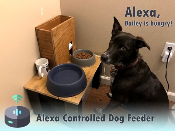
This is our dog Bailey. She’s part Border Collie and Australian Cattle Dog so sometimes she’s smarter than her own good, especially when it comes to telling time and knowing when she should be eating dinner. Typically, we try to feed her around 6 PM but this isn’t always easy if we’re away from home. The Alexa Controlled Dog Feeder was created as the perfect solution to feeding Bailey while we’re away from home to make sure she doesn’t get restless and can still keep to her schedule.
The code is based on this project from Bob at I Like to Make Stuff which takes care of the base code for communicating with an Alexa device. The nice thing about using Alexa as the main communication system is that it can be controlled using the Alexa app on your smartphone, eliminating the need for any complex servers or advanced coding. The supply list is relatively short and the entire project itself can probably be finished in an afternoon once everything is collected.
If you like what you see then please vote for me in the Pet Contest! I hope you find this Instructable helpful and let me know if you have any questions following along.
Step 1: The Design
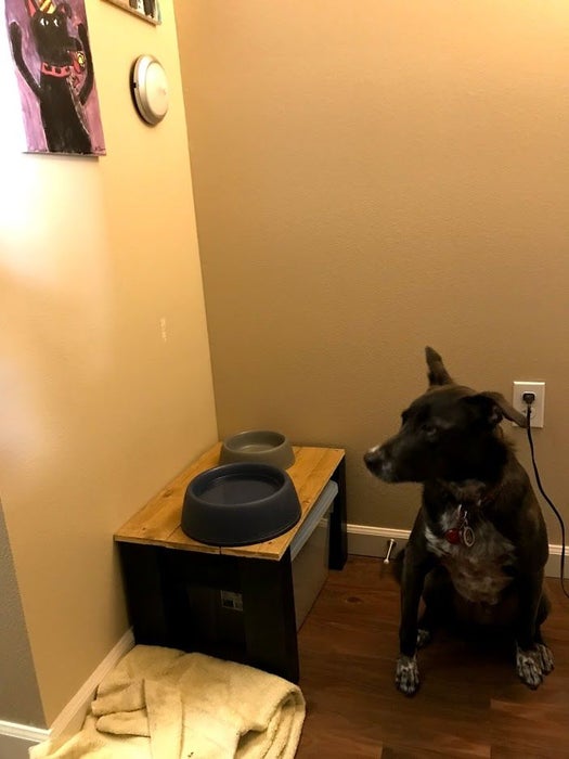
I already made Bailey a small food stand that’s a miniature version of our dining table for her food and water bowl to rest on. To optimize space I wanted the feeder to fit on this food stand and only hold a few servings of her food. The feeder is mainly supposed to be used for the small number of occasions when we’re not home so I don’t need it to fit a lot of food (just a few servings). If this doesn’t fit your needs then don’t worry as the dimensions can be scaled up or down pretty easily. The electronics will stay the same and you can adjust your feeder structure around them to fit your needs.
The structure itself is made up of two main chambers: one for the food and one for the electronics. The food will drop down from the containment area and into a PVC pipe. The PVC pipe is inside the electronics containment area which houses two PVC T-pipes with a motor and 3D printed auger running through the pipes. Once the food drops into the first PVC pipe it’ll be moved linearly by the auger until it drops out the second PVC pipe and down into the bowl. Upon testing the auger I’ve noticed it jams occasionally and causes the motor to stall. In future versions I plan on looking at this mechanism further to minimize this from happening. Again, the nice thing about this project is the main guts (i.e. electronics) can be adapted easily for whatever food delivery mechanism you decide on.
I chose to make the structure itself out of 1/2″ plywood I had lying around. The pieces are assembled using a mix of wood glue and pocket hole screws to make sure they’re secure. I also chose to use a leftover piece of acrylic for the top to make it easy to fill the food back up and see how much food is left.
Step 2: Materials
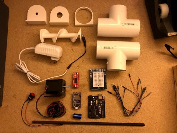
Most of the materials can be purchased from your local hardware store and Amazon for cheap. The exception for this is the PVC pipe supports that are 3D printed, however you could get creative with pipe mounts and end caps to avoid this. The PVC pipes also need to be cut down so they’re 2.75″ long in order to fit within the structure.
Materials Used:
1. 1/2″ Plywood
2. 1/8″ Acrylic
3. M8 Threaded Rod (6.5″) and Nuts (if needed to secure Auger to Rod)
5. NEMA 17 Motor and Bracket
6. 6.35mm to 8mm Coupler
7. Arduino UNO
8. Node MCU
9. Stepper Motor Driver
10. Jumper Wires
11. Pocket Holes Screws
12. Wood Glue
13. Arduino Power Supply (9V-12V)
Tools Used:
– Circular Saw
– 3D Printer
– Pocket Hole Jig
– Soldering Iron (optional, but helpful)
– Heat Shrink Tubing or Electrical Tape
– Hot Glue Gun
Read more: Alexa Controlled Dog Feeder
- What is the Alexa Controlled Dog Feeder used for?
It dispenses scheduled meals remotely via Alexa to feed a dog when owners are away. - Can the feeder be controlled from a smartphone?
Yes, it can be controlled using the Alexa app on a smartphone. - What electronics are used to control the feeder?
The project uses an Arduino UNO, Node MCU, and a stepper motor driver with a NEMA 17 motor. - How is the food moved from the hopper to the bowl?
Food drops into PVC pipes and is moved by a 3D-printed auger driven by the stepper motor. - What materials are used for the feeder structure?
The structure is made from 1/2 inch plywood with a 1/8 inch acrylic top, assembled with wood glue and pocket hole screws. - Are any 3D-printed parts required?
Yes, PVC pipe supports and the auger are 3D printed. - Does the auger mechanism have any issues?
Yes, testing showed the auger can jam occasionally and cause the motor to stall. - Can the feeder be scaled for larger capacity?
Yes, the dimensions can be scaled up or down while keeping the same electronics.
