Summary of Bicycle Speedometer Display
As the name suggests, this project builds a bike display combining a speedometer and odometer using an Arduino. An infrared sensor detects a painted white patch on the wheel to count revolutions; the Arduino computes distance from wheel circumference and speed from revolution timing, displaying results on a 1602A LCD. Power comes from two 3.7V Li-ion cells in series regulated to 5V. The build uses a perf board, jumper wires, potentiometer, switch, and basic tools; total parts cost is about 15 USD (excluding bike and Arduino).
Parts used in the Bicycle Speedometer Display:
- 1602A LCD Display
- Infrared Sensor
- Jumper Wires (Male to Male) — 20x
- Jumper Wires (Male to Female) — 3x
- Arduino Uno
- PTM Switch
- Velcro Strip (1 m)
- Perf Board (10x5 cm)
- M3 Bolt
- M3 Hex Nut
- 7805 5V Voltage Regulator
- Li-Ion 3600 mAh 3.7V Batteries — 2x
- 18650 Battery Holders — 2x
- 10k Potentiometer
- Optional: Duct Tape
- White Paint
What Is It?
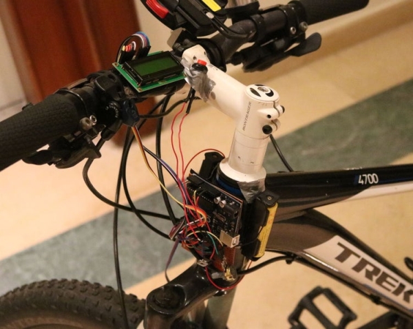
As the name suggests, in this project you will learn how to create a display for your bike that consists of both a speedometer and an odometer. Indicating real time speed and distance travelled. The total cost of this project comes to around 15 USD (not including the bike or the Arduino) yet the effort spent is worth the result.
How Does It Work?
This device works by counting the number of turns the wheel takes in a given period of time. It does this using an infrared sensor that detects the colours white and black. On the front tire, a white patch is painted on to allow the infrared sensor to detect when the wheel has made one revolution. Based on this information, the Arduino can determine the total distance travelled by the bike by multiplying the revolutions of the wheel by the circumference of the wheel. It is also able to calculate the speed of the bike by timing the intervals between consecutive revolutions of the wheel. This information is then displayed on the LCD display which is carefully positioned in the rider’s field of view.
Onto the build….
Supplies:
Part List
- 1x 1602A LCD Display
- 1x Infrared Sensor
- 20x Jumper Wires (Male to Male)
- 3x Jumper Wires (Male to Female)
- 1x Arduino Uno
- 1x PTM Switch
- 1m Long Velcro Strip
- 1x 10x5cm Perf Board
- 1x M3 Bolt
- 1x M3 Hex Nut
- 1x 7805 5V Voltage Regulator
- 2x Li-Ion 3600 mAh 3.7V Batteries
- 2x 18650 Battery Holders
- 1x 10k Potentiometer
- Optional: Duct Tape
- White Paint
Equipment List
- Scissors
- Hot Glue Gun
- Solder
- Soldering Iron
- Computer
- Arduino Uno Cable
- Arduino Software
- Paint Brush
Step 1: Circuitry: the 1602A Liquid Crystal Display
Required Parts And Equipment:
- 12x Jumper Wires
- 1x LCD Display
- Soldering Iron
- Solder
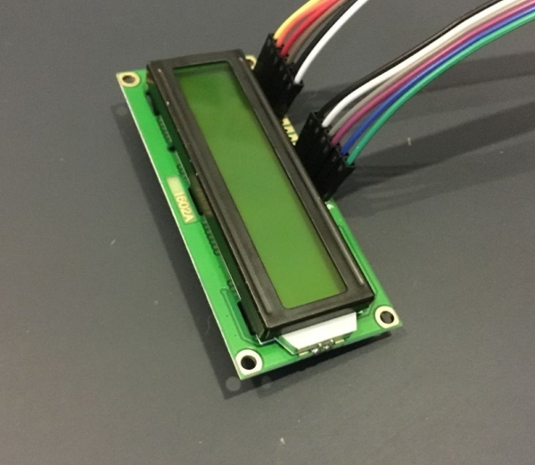
First, lets take out the LCD Display. It’s important to remember that only 12 of the 16 pins actually need to be soldered to jumper wires. These pins are the 6 pins on either end of the strip of ports. Using a solderingiron, we can permanently join the wires to these ports as seen in the photos above.
Don’t use too much solder as it may lead to the creation of a short between two pins yet using too little may result in an improper or dry joint that doesn’t conduct electricity. So be careful to manage the amount of solder you use per pin.
Step 2: Circuitry: the Arduino and Perf Board
Required Parts And Equipment:
- 1x Arduino Uno
- 1x 10k Potentiometer
- 5x Jumper Wires
- 1x Perf Board
- 1x M3 Bolt
- 1x M3 Hex Nut
- Soldering Iron
- Solder
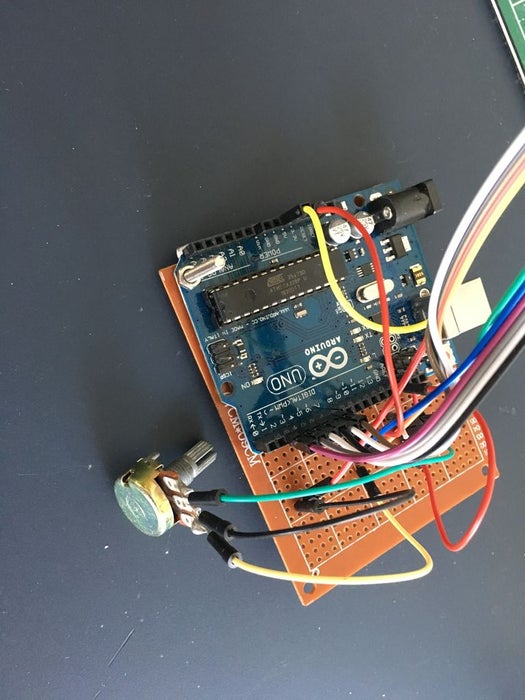
- Attach the Arduino Uno to the Perf Board by lining up one hole from the UNO and one from the Perf Board and then securing the two with an M3 bolt and hex nut. Blue tack, tape or hot glue may be used for additional stability.
- Connect the LCD Display to the necessary Arduino pin ports as per the diagram above. The perf board may be used to join many jumper wires that are connected to the same terminal. E.g. Positive and GND.
- Solder the potentiometer pins to jumper cables and connect those cables to the necessary ports as illustrated by the diagram above.
Step 3: Circuitry: the Infrared Sensor
Required Parts And Equipment:
- Infrared Sensor
- 3x Male to Female Jumper Wires
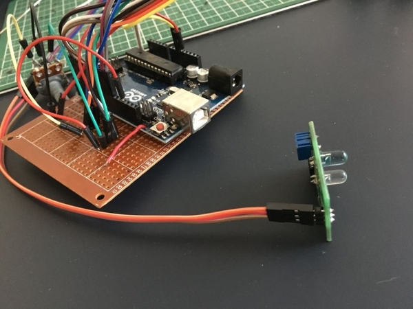
This is the sensor that will detect the number of rotations of the wheel and relay that information to the Arduino module.
Connect the jumper wires to the Infrared Sensor and then to their respective Arduino pins as illustrated the diagram above.
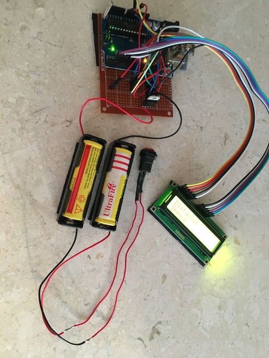
Step 4: Circuitry: Power Input
Required Parts And Equipment:
- 2x Li-Ion 3600mAh 3.7V Batteries
- 2x Li-Ion Battery Holders
- 1x PTM Switch
- 1x 7805 5V Voltage Regulator
- Soldering Iron
- Solder
Explanation
Since the bike will be moving, it requires a portable power source. The Arduino Uno board can be externally powered by a 5V source which is where the 2 Li-Ion batteries come in. Each cell is 3.7V, and therefore in series, it provides a total voltage of 7.2V. Hence, we require a 5V regulator to step that voltage down to 5V so that the UNO is supplied with 5V.
Process
First solder the voltageregulator to the perf board as shown in the images above. Then solder the positive terminal of one battery holder and the negative terminal of the other battery holder to relevant pins on the 7805 (see schematic above).
The switch should be soldered between the two batteries so that when closed, it creates a series circuit. Finally, place the batteries in the holders and connect the outputs from the 7805 to the V (in) and GND pin on the Arduino.
Read more: Bicycle Speedometer Display
- What does the project build?
A bike display combining a speedometer and an odometer using an Arduino, infrared sensor, and 1602A LCD. - How does the device detect wheel revolutions?
It uses an infrared sensor to detect a painted white patch on the front tire each time the wheel completes a revolution. - How is distance calculated?
The Arduino multiplies counted wheel revolutions by the wheel circumference to determine distance travelled. - How is speed calculated?
The Arduino times intervals between consecutive wheel revolutions to calculate real-time speed. - What powers the Arduino on the bike?
Two 3.7V Li-Ion batteries in series provide 7.2V, which is regulated down to 5V by a 7805 voltage regulator for the Arduino. - Which LCD pins need soldering?
Only 12 of the 16 LCD pins need to be soldered—the six pins on either end of the port strip. - How is the Arduino secured to the perf board?
By aligning a hole from the Arduino and the perf board and fastening them with an M3 bolt and M3 hex nut; additional tape, blue tack, or hot glue may be used. - Where are the battery switch and regulator placed?
The switch is soldered between the two batteries to create a series circuit; the 7805 regulator is soldered to the perf board and its outputs connect to the Arduino V(in) and GND. - What is the estimated total cost?
The total cost is around 15 USD, excluding the bike and the Arduino.