Summary of Rob the Automated Robot
This article guides users in building "Rob," an automated obstacle-detecting robot for a university project. It details the assembly process, including soldering motors to wheels, connecting components via a Motor Shield and Arduino, and integrating sensors using 3D-printed parts. The robot uses ultrasonic and touch sensors to navigate safely around obstacles without requiring advanced programming knowledge.
Parts used in Rob the Automated Robot:
- Arduino UNO
- Motor Shield
- Breadboard
- DC Motors
- Wheels
- HC-SR04 Ultrasonic Sensor
- 9-V battery Holders
- Micro Servo Motor
- 9V Batteries
- Electrical Tape
- Wires
- Black Box
- Touch Sensor
- Hot Glue Gun
- Soldering Iron
- 3-D Printer
- Screwdriver
- Wire Cutters
This instructable was created in fulfillment of the project requirement of the Makecourse at the University of South Florida (www.makecourse.com).
In this tutorial you will learn how to make a fully automated robot named Rob who is equipped with sensors that allow it to detect obstacles. Rob moves until he comes into contact with an obstacle and then he stops, checks his surroundings and continues on a path that is free from obstacles.
To create this robot, a knowledge of Arduino and C++ isn’t necessary but it does help!
Let’s get started!
Step 1: What You Will Need
For this project, you will need:
Materials:
- Arduino UNO x1
- Motor Shield x1
- Breadboard x1
- DC Motors x4
- Wheels x4
- HC-SR04 Ultrasonic Sensor x1
- 9-V battery Holders x2
- Micro Servo Motor x1
- 9V Batteries x2
- Electrical Tape
- Wires
- Black Box x1
- Touch Sensor x1
Tools:
- Hot Glue Gun
- Soldering Iron
- 3-D Printer
- Screwdriver
- Wire Cutters
Step 2: Prepare Wheels
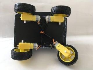
Take two jumper wires and place one through each of the copper tabs found on the side of a DC Motor. Using a soldering iron, carefully solder the jumper wires to the DC motor. Repeat for all of the motors.
Take the wheel and position it onto the white pin found on the opposite side of the copper tabs on the DC motor. The wheel should stay on tightly and spin freely along with the DC Motor.
To check if the wheels are functioning properly, place each of the wires that were soldered onto each DC motor onto the positive and negative terminals of a 9-V battery. The wheel should spin.
Step 3: Preparing 3D Printed Components
Using a 3-D Printer, print the following .stl files. The part files are also included in case there is a need to alter the design.
Step 4: Set Up Motor Shield
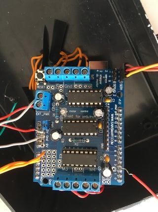
Using a screwdriver we are going to connect each of the DC Motor wires onto the M1 M2 M3 and M4 ports on the Motor shield.
Connect the motors that will be control the left wheels onto the M1 and M2 ports and the right wheel motors onto the M3 and M4 ports.
If a motor is running backwards, simply switch the wires on the Motor shield port for that wheel. (Essentially switching the positive and negative connections).
Solder long Wires onto the +5V, Ground, A0, A1, and Pin 3 on the motor shield. These will be used to connect the Breadboard, Ultrasonic Sensor and the Touch Sensor in later steps.
Using a screwdriver, connect a battery holder to the EXT_PWR port on the motor shield. This will provide power to the motor shield and the wheels.
Place the Motor shield onto the Arduino, making sure that the ports are properly aligned.
Step 5: Connect to the Breadboard
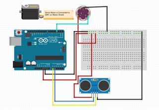
To keep things simple, most connections are soldered onto the motor shield. The breadboard is mainly used to provide +5V and Ground connections.
Using the wires soldered onto the Motor shield in the last step, connect the +5V wire to the red power strip of the bread board and connect the Ground wire to the blue power strip on the breadboard.
Step 6: Set Up the HC-SR04 Ultrasonic Sensor
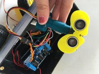
For this part, you will need your 3-D printed parts from step 3!
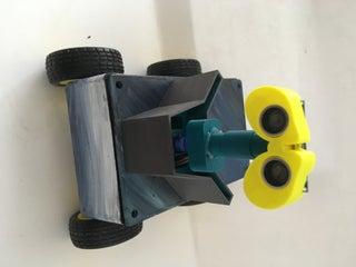
Fit the Ultrasonic Sensor into the 3-D Printed Ultrasonic Sensor Holder part. Connect 4 female to female jumper wires to the Ground, Trigger, Echo, and VCC ports found on the back of the ultrasonic sensor. Run the jumper wires through the inside of the Servo Mount Part and using hot glue, connect the servo mount part to the Ultrasonic Sensor Holder part.
Connect the wires that were soldered onto the motor shield in step 4 to the end of the ultrasonic sensor female to female connection.TRIG should connect to A0, and ECHO should connect to A1. Run a connection from the red power strip on the breadboard to the VCC port on the ultrasonic sensor and another connection from the blue power strip to the GROUND port.
Secure connections with electrical tape to ensure the they do not become loose.
Step 7: Set Up the Servo Motor
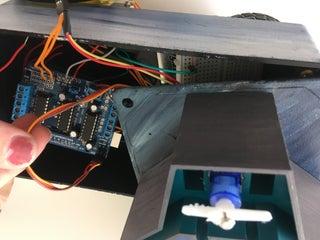
For this step, you will need the Base 3-D printed part.
Fit the Servo Motor onto the center opening (The middle opening of the 3 rectangular openings) of the Base 3-D printed part. Run the Servo Wires through the opening and connect the servo motor onto the SER1 port on the corner of the motor shield.
Hot glue the Ultrasonic Piece from the previous step to the top of the servo motor.
Step 8: Set Up the Touch Sensor
Connect 3 female to female jumper wires to the G,V and S ports found on the back of the touch sensor.
Connect the wire soldered onto pin 3 of the Motor shield to the S port on the touch sensor. Run a connection from the red power strip on the breadboard to the VCC port on the ultrasonic sensor and another connection from the blue power strip to the GROUND port.
Source: https://www.instructables.com/Rob-the-Automated-Robot/
- How do I prepare the wheels for the DC motors?
Solder jumper wires to the copper tabs on the motor and position the wheel onto the white pin on the opposite side. - What ports on the Motor Shield connect to the DC motors?
The left wheel motors connect to M1 and M2, while the right wheel motors connect to M3 and M4. - How is the ultrasonic sensor connected to the system?
Connect the TRIG wire to A0 and the ECHO wire to A1 on the motor shield, then power it via the breadboard. - Where does the Micro Servo Motor attach?
Fit the servo into the center opening of the Base 3-D printed part and connect its wires to the SER1 port on the motor shield. - Can I build this robot without knowing C++ or Arduino?
No, knowledge of Arduino and C++ is not necessary but it helps. - How do I verify that the wheels are functioning properly?
Place the soldered wires from each motor onto the positive and negative terminals of a 9-V battery to check if the wheel spins. - What is the purpose of the black box in this project?
The article lists the black box as a required material but does not specify its exact function in the text. - How do I secure the connections for the ultrasonic sensor?
Secure the connections with electrical tape to ensure they do not become loose.