Summary of Arduino Robot Catapult
Summary: A DIY robotic catapult with auto-loading magazine and hands-free IR controller. It uses multiple servos, an Arduino Uno, a WS2812 LED ring for animations, and two IR obstacle sensors to aim and fire. The project includes 3D-printed parts and guidance on wiring, power, and nonblocking code techniques.
Parts used in the Robot Catapult:
- 15 mm balls (bullets)
- 3D printed parts (catapult and controller top & bottom)
- 2x MG995 Servo motors
- 2x SG90 9G Servo motors
- Arduino Uno Board
- Arduino Uno sensor shield
- Power supply (2A, 5V recommended)
- 20x M3 Screws
- 20x M3 Nuts
- 20x M3 Brass nuts (inserts)
- 8x M2 screws & nuts
- 2x IR Infrared Obstacle Avoidance Sensor (for controller)
- RGB LED Ring 12 Bit WS2812 5050 (NeoPixel ring)
- 1x M3 Screw & Brass nut (for controller)
Hello there fellow makers,
This instructable is my attempt to make a robot for the ‘ROBOTICS CONTEST’ competition in instructables. So here it is 🙂
I’ll start this instructable with a joke 🙂
Q: what’s the difference between men and boys?
A : the price of the toys
Having said that, lets make a toy!
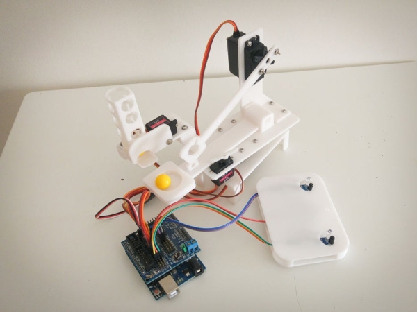
What I wanted to accomplish is a fully automated, easy to use, robotic catapult. To add some more challenge I wanted the catapult to have an ‘auto-load’ feature, which means that there should be a magazine and loading mechanics.
As you can see in the video below, you can load balls in the magazine and the robot catapult will do the hard work for you. While designing the catapult I was looking for an easy method of controlling the catapult and came up with a ‘hands free’ controller.
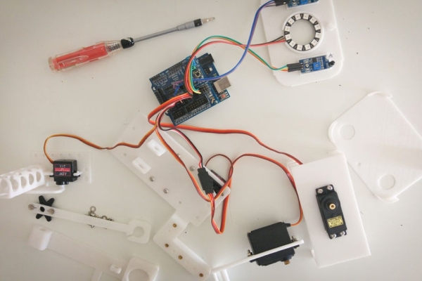
Part List :
15 mm balls (bullets)
3D printed parts, can be found here
2x MG995 Servo motors
2x SG90 9G Servo motors
Arduino Uno Board
Arduino Uno sensor shield ( for easy motor connection )
Power Supply ( 2A , 5V recommended )
20x M3 Screws
20x M3 Nuts
20x M3 Brass nuts (insert)
8x M2 screws & nuts
Part List for the controller :
3D printed parts, can be found here and here (controller top & bottom)
2x IR Infrared Obstacle Avoidance Sensor
RGB LED Ring 12 Bit WS2812 5050
1x M3 Screw & Brass nut
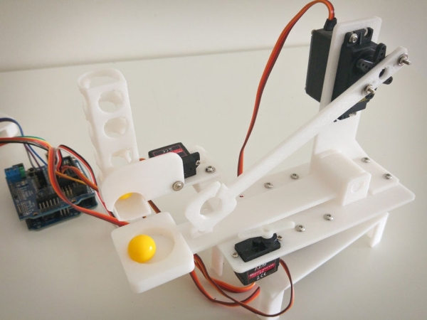
Step 1: Assemble the Catapult
Assembling the catapult is really easy, just connect the parts as shown in the images above. Please note that M3 brass nuts have be inserted by applying heat. You can use a soldering iron for this.
Step 2: Let the Beast Come to Life!
Ok, you have your catapult assembled and ready to have some fun! Now you’ll have to add some code to bring your new toy to life.
Connect the servo’s :
Servo motors work by applying a PWM (pulse width modulation) signal, which sets the servo motor position. To control servo motors from arduino you’ll have to use PWM pins ( 3,4,5,6,9,10 in Arduino UNO ), I’ve connected my servos as follows :
- Base motor – pin 9
- Tray motor- pin 6
- Arm motor – pin 5
- Tray lock motor – pin 3
Add some power :
You should not rely on your Arduino’s power supply to power your servo’s. An external power supply should be used (a 2A 5V should be enough). Connect the sensor shield to your power supply and make sure to set the sensor shield to use an external power source (by removing power select jumper).
Make it move!
You can use my code to bring your catapult to life, but I wish to challenge you to do it on your own!
If you’re new to arduino/programming here are some tips for you:
- Here’s a basic guide on how to use servo motors with arduino,
- Start with one motor and then add the others.
- Servo motors tend to react quickly, that’s not what you want. Add some code/delay to create a sweep effect when the motors move.
- Write your code like a story, make sure it’s readable. For example use proper naming for your variables (‘baseMotor’ and not ‘motor1’)
- Your catapult can load ‘bullets’ automatically from tray magazine, timing can tricky
Step 3: Add Animation With Led Ring

In this step we will add some animation and hands free remote control for our catapult! We will use led ring with 2 IR sensors to control our toy.
This will work as follows :
- In idle mode an animation will be played
- Blocking right IR sensor, catapult will turn right
- Blocking left IR sensor, catapult will turn left
- Blocking left and right IR sensors, catapult will fire
Some challenges and how to overcome them :
- Playing animation can block our code while sampling IR sensors, to resolve this I’ve used non blocking delay in Arduino.
- NeoPixel library and Servo code doesn’t play nice together, I’ve solved this by using Software Servo Library. Pleae note that the library have compilcation issues with the latest Arduino versions, to solve replace “#include “WProgram.h” with “#include “Arduino.h”
Source: Arduino Robot Catapult
- What is the purpose of the project?
To build a fully automated robotic catapult with an auto-load magazine and hands-free IR controller. - Which servos are used and how many?
Two MG995 servos and two SG90 9G servos are used. - Which Arduino pins are used for the servos?
Base motor on pin 9, tray motor on pin 6, arm motor on pin 5, and tray lock motor on pin 3. - What power supply is recommended?
An external 5V power supply rated at about 2A is recommended for the servos. - How does the hands-free controller work?
The controller uses two IR sensors and a NeoPixel LED ring: block right sensor to turn right, block left sensor to turn left, and block both to fire; idle plays an animation. - How are M3 brass nuts inserted in 3D printed parts?
M3 brass nuts are inserted by applying heat, for example using a soldering iron. - How are NeoPixel animations and servos coordinated?
The project uses nonblocking delays and the Software Servo library to avoid blocking while sampling IR sensors and running NeoPixel animations. - Can I power servos from the Arduino board?
No; the article advises against relying on the Arduino power supply and recommends an external power source.