Hey! This I’ble is now out of date!
I made an updated version which you can read here! Hope you find it fun and useful!
~~~~~
Thus far, I’ve shown you how to create wheels out of household items, severalmotorizedchassis out of cardboard, and a couple of simple and effective light sensors. Now, one of the last major pieces is about to fall into place.
Almost every robot needs to power a motor of some sort or another. Problem is that motors take quite a lot of power, compared to what most microcontrollers operate with. To solve this problem, robots use what is called a motor controller, which usually amounts to some form of electronic switch that can turn on a very high voltage, using a very low one. That’s what we’ll be making today!
Let’s get started!
~~~~~
For more Instructables on building cheap robots, please check out the For Cheap Robots collection! For more things that I’ve done, you can check out my profile page!
For more info from Digilent on the Digilent Makerspace, check out the Digilent blog!
Step 1: What You’ll Need
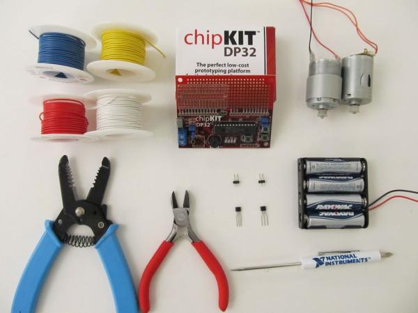
For this project, you’ll need the following:
- At least two colors of wire.
- I use solid-core wire. It’s pretty standard to use red for power and black for ground, but my black is running low so I picked white.
- (Optional) Two more colors of wire.
- It can be helpful to organize your signal wires by color. I’m using yellow and blue.
- The DP32 from Digilent.
- Most any microcontroller board will do, but the DP32 is cheap and has a built-in breadboard where you can wire everything.
- A couple of motors.
- These ones I salvaged from a couple of old, broken printers.
- A battery pack.
- I usually use four AA or AAA batteries, because that works well for most microcontroller boards.
- A screwdriver.
- This is just for screwing in your battery leads.
- Wire cutters and wire strippers.
- Two negative transistors.
- I’m using the N-FET transistors from Digilent’s chipKIT starter kit. Make sure you’re using N-FETs and not BJTs (NPN or PNP transistors), as BJTs are more complicated than MOSFETS.
- Mine are part number ZVN2110A, in case you were wondering.
- Two sets of two header-pins each.
You’ll also need (but are not pictured):
- A soldering iron.
- (Optional) A hot glue gun.
- I only used this for my header pins, so if you don’t have any of those, you don’t need it at all!
Step 2: Circuit Diagram
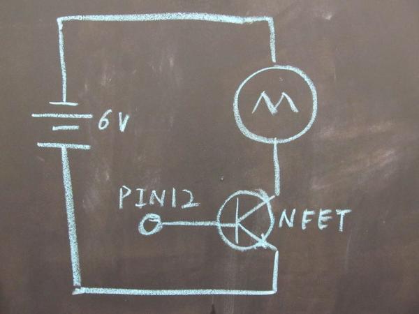
I’ve received some requests for circuit diagrams for this and my line sensor tutorial, but it’s always been my intent to provide one for you folks. However, I still haven’t found a circuit diagramming program that I’m completely happy with. Instead of making you folks wait, I figured I would just use one of the black boards we have around the Digilent Makerspace, to draw up a quick diagram and explain what’s going on.
This circuit is extremely simple, as you can see. The motor is connected directly to the 6 volt output of the batteries that power our board (no regulators or anything). Then, it’s connected to ground through our N-FETs, and the gate pin of the N-FETs are connected to one of our DP32’s output pins.
What this allows us to do is use the N-FET like an electronic switch, turning our motors on and off. N-FETs are also very fast, so if you wanted to you could switch the motor on and off very rapidly, effectively giving it less power to make it run slower! What this circuit can’t let us do is change the direction that our motor runs. For that, you’ll need a more complicated circuit.
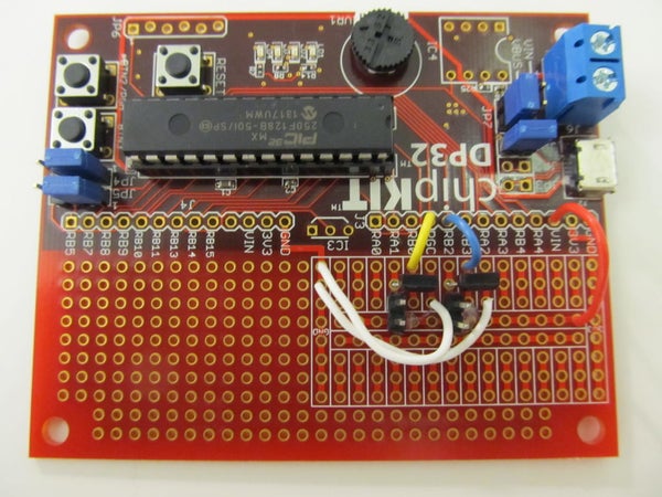
Step 3: Installing Transistors
This step is best explained by the pictures above, however I’d like to add a couple things here.
Firstly, it’s very important to know which lead is which on your transistors. In the case of my N-FET transistors, Drain (the leftmost pin) connects to the higher voltage (in this case my motor’s negative lead), while Source (the rightmost pin) connects to ground. You can tell which direction these N-FETs are facing because the “front” is slightly rounded (which you can see in picture 2).
For BJT transistors (of which NPN transistors are one type) it’s very. My partner in crime brmarcum has a tutorial all about using BJTs, but you’re going to want to avoid them for this tutorial.
Secondly, I’d like to point out that I chose where I placed my transistors very carefully, so that this tutorial would be fully compatible with my Line Sensor tutorial.
Read more: Motor Controllers for Cheap Robots