Summary of Sound Localization using Arduino
This project demonstrates precise sound localization using Arduino by measuring phase differences between signals from two widely spaced electret microphones. Unlike common Time Difference of Arrival methods, it utilizes phase delay and FFT algorithms to achieve sub-millimeter resolution at 10 kHz frequency, enabling detection of sound source position with high accuracy. The system processes signals from four microphones in two coordinate dimensions, using efficient look-up tables for phase calculations and custom "Rolling Filters" for noise reduction. It manages hardware constraints and sampling rates to successfully track and classify objects in 3D space based on sound characteristics.
Parts used in the Sound Localization using Arduino:
- Arduino board with AtMega328 microcontroller
- 4 Electret microphones
- 9 Resistors
- 4 Additional resistors (mentioned separately)
- Small number of capacitors
- 1 Integrated circuit (unspecified type)
In theory, it is quite simple to perform sound localization by measuring the phase difference of signals received by two microphones that are far apart in space. The devil is always in the details. I have not come across any project made for Arduino like this before, and I am wondering if it is even possible. In short, I want to introduce my project that answers this question with a resounding YES! I want to emphasize that the project is based on phase delay, not TDOA. Results of measurements indicate that the current version of the software has a minimum detectable phase offset of 1 degree, as shown in both copies of the source code linked below, which differ only in filtering techniques.
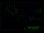
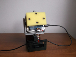
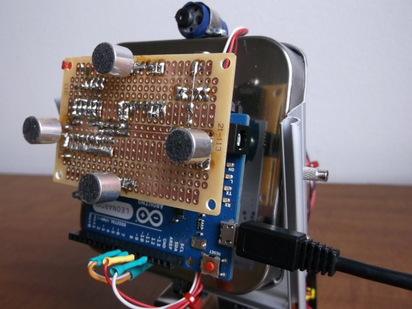 This provides incredible specific clarity. An instance is a 10 kHz sound wave, with a 34-millimeter length in the air, divided by 360 degrees to give roughly 0.1 millimeters per degree of phase shift. Certainly, the further an object moves from the microphones, the less accurate the measurements will be. The crucial aspect is the ratio of the distance to the object compared to the distance between the two microphones (base). The device shown in the video has a base of 65 millimeters and is able to accurately detect location along a horizontal line with a precision of 1 meter up to a distance of 650 meters. In theory. Additionally, the amount of electronic components does not vary significantly from those I utilized in my last blog post. When you compare the two drawings, you will see that only 4 resistors and 4 electret microphones were included. The entire setup consists of only a small number of capacitors, 9 resistors, a single integrated circuit, and microphones. To be honest, when I wrote a remix of the oscilloscope, I was experimenting with the analog inputs of an Arduino. My goal was to eventually use it along with electret microphones in future projects, such as sound pressure measurements, voice recognition, or something amusing in the “Color Music / Tears of Rainbow” series. What they refer to as a “pilot” project? When utilizing 4 channels (specifically settings 7, 8, and 9 Time/Div) for fast rate sampling, the simplest oscilloscope encounters some issues, as previously mentioned. In order to address this, I have slightly decreased the sampling rate to 40 kHz.
Note: *The same applies to Arduino Leonardo in all of the above cases. The hardware and software requirements vary for arduino boards depending on the different chips used, and must feature pre-amplifiers with AtMega328 microcontroller. Another crucial point to note in this brief introduction is the utilization of the FFT algorithm for phase calculation. Arduino can not only track a flying object in 3D space, but it can also differentiate the object based on its spectral characteristics of the emitted sound. It can identify whether it’s an aircraft or helicopter, determine the type/model, and even distinguish between male and female insects.
SOFTWARE
As I say above, I choose 40 kHz for sampling rate, which is a good compromise between accuracy of the readings and maximum audio frequency, that Localizator could hear. Getting signals from two mic’s simultaneously, upper limits for audio data is 10 kHz. No real-time, “conveyor belt” include 4 major separate stages:
- sampling X dimension, two mic’s (interleaving);
- FFT
- phase calculation
- delay time extracting
- sampling Y dimension, two mic’s;
- FFT
- phase calculation
- delay time extracting
4 mic’s split in 2 groups for X and Y coordinate consequently. Picking up 4 mic’s simultaneously is possible, but would reduce audio range down to 5 kHz, so I decided to process two dimension (horizontal and vertical planes) separately, in series. Removing vertical tracking from the code, if it’s not necessary, would increase speed and accuracy in leftover plane. I’d refer you for description of the first and second stages to other blogs, FFT was brought w/o any modification at all. Essential and most important part of this project, stages 3 and 4.
Phase Calculation (3).
I am not skilled at teaching mathematical concepts, so it is recommended to find another source for a tutorial on the topic. The heart of the process is the arctangent function. This link contains information about several cycles. In just two words – too sluggish. Look Up Tables, known as LUTs, are the optimal choice for non-floating point microprocessors to efficiently perform intricate mathematical calculations at high speeds with a decent level of accuracy. The limitation of LUT is its small size, so it may be stored in FLASH memory, which is also restricted in the next stage. This is how I approached the “resource management” aspect: 1 kWords (16-bit integers, 2 kBytes), 32 x 32 (5 x 5 bits) LUT, increased to 512 for improved “integer” precision. A few values in the upper-right corner have merged because their variations are less than “1” (not visible in the picture on the right). The least favorable resolution is found in the upper-left corner, where the granularity has reached 256, or half of the dynamic range is deemed unacceptable. In order to avoid this corner, I installed a “Rainbow Noise Canceler” that includes a single line with an “IF” statement to disqualify any BIN with FFT magnitude under 256.
IF (((sina * sina) + (cosina * cosina)) < 256) phase = -1;
I named it “Rainbow” due to its shape, where the “red line” is an arc that stretches from 16 on the top line to 16 on the left side. Additionally, the “Gain Reset” setting, originally 6 bits for an FFT size of 128, was decreased to 5 bits to improve sensitivity. These two configurations, 5-bit and 3.5 bit magnitude (256) constraint, establish a “threshold” for faint spectral peaks. Essentially, the adjustment of both values can vary in different ratios based on the application.
There are two types of tracking techniques, one with microphones installed on a moving platform and the other with stationary microphones. The first one is slightly simpler to comprehend and construct, it measures the relative direction to the sound source. This is what I have accomplished. When the laser pointer (or filming camera) is moving by itself, the stationary microphone’s method needs to determine the exact direction of the sound source and must involve step #5 – calculating the angle using the known delay time. Mathematics is quite straightforward, using the arccsine function, and at this stage of the program, only one calculation every few frames would be required, so floating point mathematics would not be a problem. No Look-Up Table (LUT) will be used, no scaling, and no rounding or truncation will be performed. All you require is a basic understanding of elementary school geometry.
Delay Time Extraction (4).
Phase difference is generated by subtracting the phase value of one “qualified” microphone’s data pull from another. To convert phase difference to delay time, the BIN number is divided. We will name this process “Denominator” operation. The denomination is crucial as all data, regardless of wavelength variations in each bin, will be grouped and processed together after this step. There is a simple formula that relates frequency and wavelength: Wavelength = Velocity / Frequency, with the velocity being the speed of sound wave in the air (340 m/sec at room temperature). The constant distance between two microphones causes sound waves with varying wavelengths (frequencies) to have different phase offsets, which then become proportional through calculation. (WikiPedia would definitely provide a clearer explanation, but remember, I am a Magician, not a mathematician).
The initial image on the right side displays the correction for “Nuisance 3: Incorrect arctan.” In the code concerning stage #3, there are two “IF” statements.
The second image illustrates the need for an additional correction in stage #4. When subtracting one arctan function from another, a rectangular “pulse” is generated when one function changes sign while the other (delayed version) does not. (Difference in correction shown in violet line) There is no abnormality in the light blue line (DIFF(B)). Math is easy, just two lines with the same “IF” statements, only this time with constants that are twice as big. 2048 on my scale is equivalent to 2 times PI, 1024 is equal to PI, and 512 is equal to PI divided by 2.
Arduino features a single ADC, resulting in a fixed delay of one sampling period ( T = 1/40 kHz = 25 microseconds), which must also be accounted for (either subtracted or added, depending on how you assign input 1 and 2 – left / right side microphone).
Filtering.
In order to combat reverberation and noise, I opt for a Low Pass Filter, which I would refer to as a “Rolling Filter” in this context. My investigation on standard LPF has revealed that this category of filters is not suitable at all for this kind of data because they are highly prone to “spikes”, or sudden increases in magnitude level. When the system receives consistent readings from 2-3 test frequencies at low levels, averaging the results can be disrupted by a single spike of +2000 during the next 60-100 frames. The Median Filter effectively removes abrupt spikes, yet it significantly consumes CPU resources due to its use of the “sort” algorithm every time a new sample is added to the data set. With 64 frequencies and filter kernel set at 5 – 8 samples, Arduino would be overwhelmed sorting at nearly 40 ksps. Processing all frequency data at once and sorting a single array of 64 elements is still a very time-consuming task. After some contemplation, I reached the conclusion that the “Rolling Filter” is nearly as effective as Median, but instead of needing to be sorted, it only requires 1 additional operation! In the long term, the output value will gradually move towards and stabilize around the center of the pull. ( Experiment with this in LibreOffice. ) By changing the “step” of the “Rolling Filter,” you can easily control responsiveness, a task that is nearly impossible with Median Filters. Tasks include adapting filters and making real-time adjustments based on the quality of input data.
Source: Sound Localization using Arduino

